Download
1 / 30
300 likes | 429 Views
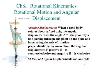
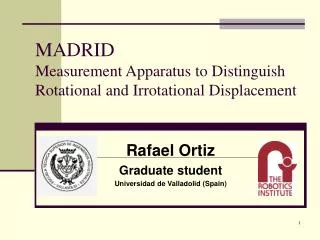
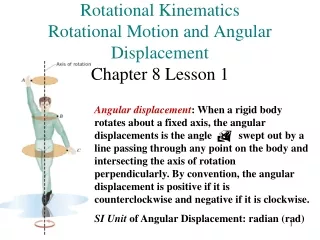
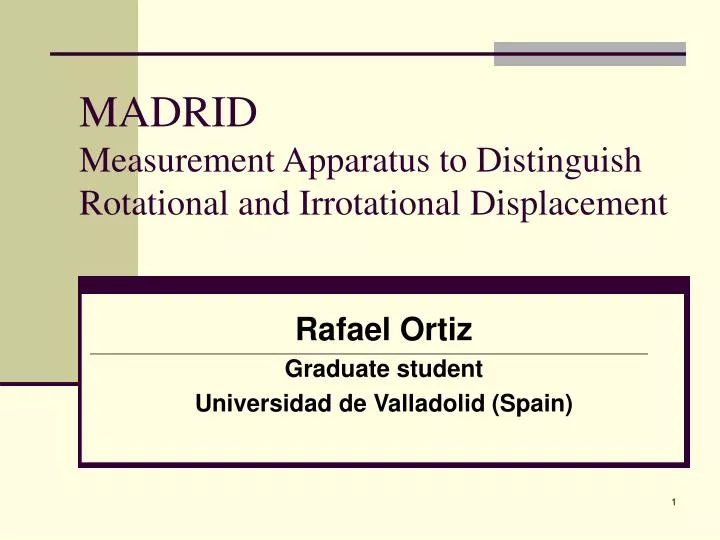
MADRID Measurement Apparatus to Distinguish Rotational and Irrotational Displacement. Rafael Ortiz Graduate student Universidad de Valladolid (Spain). MADRID. Problem to solve Reasons of choosing this option Description of the device First result Conclusion. Introduction.

E N D
MADRIDMeasurement Apparatus to Distinguish Rotational and Irrotational Displacement Rafael Ortiz Graduate student Universidad de Valladolid (Spain)
MADRID • Problem to solve • Reasons of choosing this option • Description of the device • First result • Conclusion
Introduction • High accuracy in microsurgery • Vitreoretinal microsurgery MICRON • Neurosurgery LASER MICRON • Involuntary movement of the hand hinder the desired accuracy. • Tremor • Jerk • Drift
Vitreoretinal microsurgery • Five degree of freedom • Two rotation • Three translation • Tip tracking ↓↓↓ ASAP
Vitreoretinal microsurgery • Four degree of freedom • Two rotation • Two translation • Laser tracking ↓↓↓
Options to solve the problem • Gyros. • CCD camera • MADRID
Use a par of gyros • Translation information is missing • Device should be useful for laser micron calibration. • Impossible to set a gyros above a laser ray
CCD camera • High speed ( 100 fps ) • High accuracy ↔ High resolution • Very expensive system
B1 g B2 A1 A2 MADRID • First idea: Only two dots are required to draw a line. • If the laser is tracking in two different positions , the angle may be calculated Point 1 Point 2
Configuration Power Inverse Bias Position Sensing Detector #1 DATA output Band pass Optical filter Standard Cube Beam splitter Position Sensing Detector #2
Bandpass optical filter • Benefit: eliminate most of the ambient light • Type: 10LF20-670 • C. Wavelength: 667.3nm • FWHM: 19.4nm • P. Transmission: 53.1% 10LF20-670, Newport, Irvine, CA
Laser Diode • Focusable Laser • Features: • CWWavelengths670nm ±10nm, • DiameterLDM, Circular: 5mm; • Focus Range LDM, Circular: 150mm to Infinity; Spot Size (mm) at Distance NT38-920,Edmund optics, Barrington, NJ
Standard Cube Beamsplitter • BS CUBE STANDARD 12.5MM TS • Size: 12.5mm x 12.5mm • Reflection : 50 % • Transmission : 50 % NT45-111, Edmund optics, Barrington, NJ
Channel Meaning Formula PSD #1 Ch0 V(x) Ch1 Sum(x) Ch2 V(y) Ch3 Sum(y) PSD #2 Ch4 V(x) Ch5 Sum(x) Ch6 V(y) Ch7 Sum(y) Position Sensing Detector • 1 cm2 square PSD & associated amplifier circuit. • Voltage analogd of the X,Y and spot intensity • Reverse Bias is applied DL 100- 7PCBA ,Pacific Silicon Sensor Inc. ,Westlake Village, CA
- æ ö x x a = ç ÷ 1 2 Arc tan - a d è ø - æ ö y y b = ç ÷ 1 2 tan Arc - a d è ø Calculation of two angles
( ) ( ) = - + + a g x 1 a b c tan x ( ) ( ) = - + + b g y 1 a b c tan y ( ) ( ) = - + + a g x 2 d b c tan x ( ) ( ) = - + + b g y 2 d b c tan y Calculation of displacement
General Scheme Band pass Opt filter PSD#2 Beam splitter AD card Laser Ch7 Laser Ambient light Alpha Beta Gx Gy PSD#1 X1 Transform microns into angles and positions Subtract Offset
First Result • Different modes • Only translation • Only angle • Angle and translation
Only translation • Redundant data (alpha and beta must be null) • Two studies • Full Range (step 0.04 inch or 1mm) • Small step (step 2 mil or 50 micron)
Full Range (only translation) 8.7268 6.4684 -0.0058 -0.0058
Small Step 6.7942 4.0104 -8.8044 -2.1234
Only angles Wheel to reach different orientation of angle BETA Wheel to reach different orientation of angle ALPHA
Angle (Alpha) Range =2.5653° Maximum Error 0.0268 ° Linearity =1.04%
Angle (Beta) Range =2.2526° Maximum Error 0.0517° Linearity =2.29%
Angle in completed mode Standard derivation of error in alpha Std alpha 0.0022° ≈ 8’’ Standard derivation of error in beta Std alpha 0.0022° ≈ 8’’
Translation in completed mode Standard derivation of error in x translation Std Gx error 4.1876 micron Standard derivation of error in alpha Std Gy error 4.0152 micron