Download
1 / 11
470 likes | 985 Views
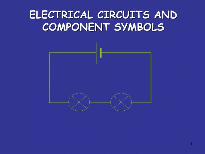
ELECTRICAL CIRCUITS AND COMPONENT SYMBOLS. Some circuit symbols. In circuit diagrams components are represented by the following symbols;. cell. battery. switch. lamp. buzzer. ammeter. voltmeter. motor. resistor. Circuit Breaker. The CELL.

E N D
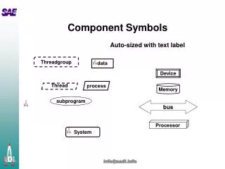
Some circuit symbols In circuit diagrams components are represented by the following symbols; cell battery switch lamp buzzer ammeter voltmeter motor resistor Circuit Breaker
The CELL The cell stores chemical energy and transfers it to electrical energy when a circuit is connected. When two or more cells are connected together we call this a Battery. The cells chemical energy is used up pushing a current around a circuit.
What is an electric current? An electric current is the flow of electrons through a circuit. - + In which direction does the current flow? from the Negative terminal to the Positive terminal of a cell.
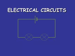
simple circuits Here is a simple electric circuit. It has a cell, a lamp and a switch. wires cell light switch To make the circuit, these parts are connected together with metal wires.
simple circuits When the switch is closed, the circuit is complete, and the lamp lights up. This is because there is a continuous path for the electric current to flow around. If there were any breaks in the circuit, the current could not flow.
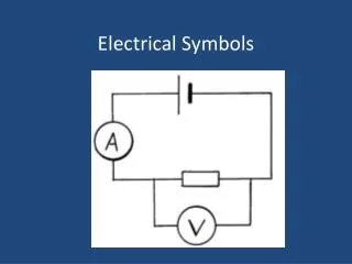
circuit diagram Electrical drawings are usually drawn using symbols; cell light switch wires
types of circuits There are two types of electrical circuits; SERIES CIRCUITS PARALLEL CIRCUITS
SERIES CIRCUITS The components are connected end-to-end, one after the other. Electrons flow in only ONE path. If one bulb ‘blows’ it breaks the whole circuit and all the bulbs go out.
PARALLEL CIRCUITS The components are connected side by side. The current has a choice of routes (MANY paths). If one bulb ‘blows’ there will still be a complete circuit to the other bulb so it stays lit.
All information researched on the following web sites. http://www.google.ca/search?q=electric%20circuit&rls=com.microsoft:en-ca&oe=UTF-8&startIndex=&startPage=1&gws_rd=cr&um=1&ie=UTF-8&hl=en&tbm=isch&source=og&sa=N&tab=wi http://www.technologystudent.com/elec1/elecex.htm www. Teachingzone.org (Electricity awareness course pack for teachers produced by C2B Media LTD