Download
1 / 31
380 likes | 452 Views
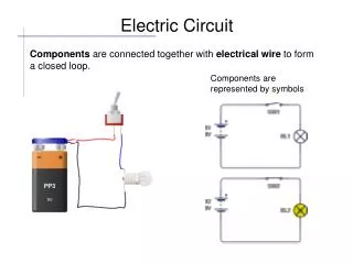
Components & Symbols Used in Electrical Circuits. Schematics & Notations. Understanding drawings, especially electrical drawings requires a keen understanding of schematics, symbols & other details used to represent components.

E N D
Schematics & Notations • Understanding drawings, especially electrical drawings requires a keen understanding of schematics, symbols & other details used to represent components. • Continual practice & a habit of reading the starter Panel drawing before attempting to troubleshoot it is the key to comprehending Electrical Starter Panels & machinery in general
Schematics & Notations • The bibliography of starter Panels on board generally contains vital information as regard how the maker has represented various components of the starter or panel internals. • Due reference to this is a must though generally parallels may be drawn form experience.
Contacts Normally Open Contact Normally Closed Contact Normally Open Contact with terminals Normally Closed Contact with terminals Start Push Button ( NO Contact ) Stop Push Button ( NC Contact )
Relays & Coils Relay coil / Contactor Coil Timer Relay Coil ( on Delay ) Timer Relay Coil ( off Delay )
Other Components Operated by pushing Operated by turning ( Latch ) Emergency Switch ( Mushroom Head Safety Feature ) Operated by pushing ( & then latches on ) Operated by turning ( spring return )
Other Components Potential Transformer / Control Transformer Secondary winding has less turns and Primary has more turns. Used for connecting volt meters Current Transformer Secondary has more turns and Primary has less turns. Used for connecting Amp meters. Indicating Lamp ( Transformer Type )
Other Components SV Heater Device fitted outside the panel ( indicated by dashed lines ) Solenoid Valve
THE RELAYS A very important component in an Electrical Circuit. A relay is a simple electromechanical switch made up of an electromagnet and a set of contacts. Relays are found hidden in all sorts of devices. In fact, some of the first computers ever built used relays to implement. Relay Construction Relays are amazingly simple devices. There are four parts in every relay: • The Electromagnet • The Armaturethat is attracted by the electromagnet • A Spring • A Set of electrical contacts
Relays Factors when looking at a relay • Coil terminals • Number of switching contact sets • Rating of the coil • Rating of the contact • Structure of the pin layout
Relay representation N/O are called ‘a’ contacts N/O Contacts This relay represented has a coil which operates on ac voltage & has 2 N/O contacts & two NC contacts. Many such possibilities may be presented depending upon the number of contacts 220 V ac N/C Contacts Coil N/C are called ‘b’ contacts
Relay Format The coil is found between terminals 2 & 10. Contacts 1 & 4 and 8 & 11 and 5 & 6 are normally closed. When the coil is energized the contact switch over to 1 & 3 ( closed ) & 11 & 9 and 6 & 7 (closed).
Relay Format 4 5 3 6 The coil is found between terminals 2 & 7. Contacts 1 & 4 and 8 & 5 are normally closed. When the coil is energized the contact switch over to 1 & 3 ; & 8 & 6 2 7 1 8 8 pin format
Analyzing the requirement Timer Relays A delay timer that waits for a predetermined amount of time before closing a set of contacts once the power is applied. T Terminals 2 & 7 Coil Set of contacts 1 Terminals 1 & 3 Set of contacts 2 Terminals 1 & 4 Time Delay ON DELAY RLEAY
Analyzing the requirement Timer Relays Relay that closes/switches on a set of contacts immediately when a coil is energized, then waits for a pre determined time to switch them off/open after the power is removed. Terminals 2 & 7 Coil Set of contacts 1 Terminals 1 & 3 Set of contacts 2 Terminals 1 & 4 Time Delay T OFF DELAY RLEAY
Contactor Auxiliary contacts Main Contacts or power contacts
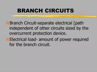
Motor starter panel routines includes inspection and maintenance of motor’s starter panel. Starter panel routines mean inspection and cleaning of contactor’s (the switch inside the starter panel box controlling the on and off of the motors) contacts. Checking of connections in the starter panel Cleaning of the complete starter panel Checks in the terminal box on the motor for loose Connections Visual inspection of overall starter panel
Safety Measures to be Followed While Starting Motor Starter Panel Routines • Switch off the main power supply from the circuit breaker • Take out the main fuses in the starter panel, and if required control fuses as well • Put the lock out tag • Inform the engineer who is in charge of that particular machinery
Thermal Overload Relay Heater coils of the thermal overload Relay Contact operated by the overload relay with resetting option. NC NO
Reading Diagrams Diagrams are always drawn in a state of rest i.e. without power – also known as the de-energized state. They are read from left to right. Generally devices with the same power level are drawn at the same horizontal level. The components are identified by two ways, Cartesian system ( co-planar ) or by a line diagram system. If the diagram runs into a few pages then reference to pages is made near the component.
There are two other differences between an AC and DC solenoid: 1) The iron core of the coil, the electromagnet, is solid for DC and layered for AC to avoid loss in iron due to eddy current. 2)The AC solenoid has a "split pole" - a part of the layered pole (around 30% of cross sectional area) has a copper ring as short circuit so that in this part of the magnet the maximum and minimum of magnetic intensity is phase shifted by 90° in respect to the main part of the pole, and therefore avoiding chattering of the solenoid by having a total magnetic force that is always well above zero when actuated.