Download
1 / 51
700 likes | 3.16k Views
Orthographic Projections and Alphabet of Lines. Fundamentals of Engineering Dr. Chuck Lockert GSMST. Objectives. Orthographic Projections View Selection Glass Box Approach First and Third Angle Projections Line Precedence Two View Drawings Tips. Orthographic Projections.

E N D
Orthographic Projections and Alphabet of Lines Fundamentals of Engineering Dr. Chuck Lockert GSMST
Objectives • Orthographic Projections • View Selection • Glass Box Approach • First and Third Angle Projections • Line Precedence • Two View Drawings • Tips
Orthographic Projections • Orthographic Projections are a collection of 2-D drawings that work together to give an accurate overall representation of an object.
Orthographic Views • You can adequately describe most objects with three orthographic views. • Front • Top • Right
Which Views to Present? General Guidelines • Pick a Front View that is most descriptive of object • Normally the longest dimension is chosen as the width (or depth) • Most common combination of views is to use: • Front, Top, and Side View • Any other view different from the Principal Views is called an Auxiliary View
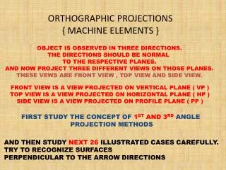
Orthographic Projections - Describing and Angle Bracket Collection of 2D drawings Accurately represent an object Let us see how the angle bracket would be drawn. 8
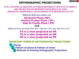
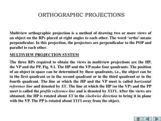
Orthographic Projection Orthographic drawings represent three dimensional objects in three to six separate views arranged in a standard manner.
Glass Box concept • Envision the object surrounded in a glass box • Project the views out onto the pieces of glass • Each pane shows a 2D projection of the object
Glass Box Approach • Most powerful technique to understand orthographic projections • Suspend the object with transparent strings inside a glass box • Freeze the view from each direction (each of the six sides of the box) and unfold the box • Animation illustrates glass-box approach
Third-angle Projection First-angle Projection First and Third Angle Projections • First Angle – International • Third Angle – U.S.
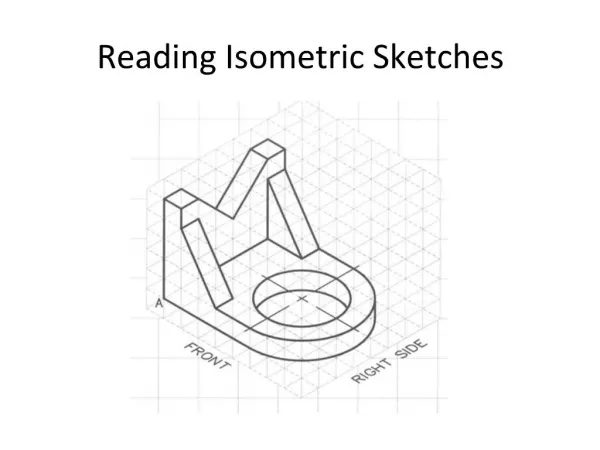
Orthographic Projection • Using the angle bracket previously introduced, an orthographic set of sketches can be produced as follows
Which Views to Present? • General Guidelines • Pick a Front View that is most descriptive of object • Normally the longest dimension is chosen as the width (or depth) • Most common combination of views is to use: Front, Top, and Side View • Views other than the Principal Views are called Auxiliary Views
Width Top View Depth Right Side View Front View Height Conventional Orthographic Views
A Box in Orthographic View Is This Orthographic View OK?
Graphical Communication • Oblique and isometric drawings are 3D and general • Orthographic drawings are 2D, more detailed, and often have dimensions for the part • Object, Hidden, Centerline, and Construction are 4 common types of lines used in engineering graphics
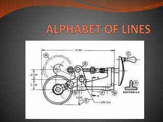
Line Types Object Line Hidden Line Center Line Dimension Line Construction Line
Dimensioning Standards • Standards are different in different career areas. • Civil, Electrical, Construction and other areas follow similar practices, but sometimes with less need for precision in measurements. • Dimensioned drawings are a part of a contractual document.
Dimension Lines • Various means to terminating ends • arrow head • dot • tick • Normally, dimensions are shown ABOVE dimension line • If a dimension is needed for construction, it should be on the drawing • Do not include unnecessary dimensions
Dimensioning Floor Plans • Frame Construction • dimensions usually start at the exterior surface of the stud wall • interior walls usually dimensioned to the center of partitions
Window and Door Openings • Frame Construction • Located by their center lines
Window and Door Openings • Masonry Construction • Openings are dimensioned to the edges of the masonry surface openings
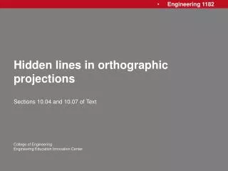
Hidden Lines – represent features that cannot be seen in the current view • Centerlines – represent symmetry and mark the center of circles, the axes of cylinders, and the axes of symmetrical parts, such as bolts Hidden and Center Lines in Orthographic Projections • Object Lines – represent visible features for an object
For Example: 1. Visible 2. Hidden 3. Center
U.S. Customary Drawing Sizes • U.S. Paper Sizes A 8.5" X 11“ B 11" X 17“ C 17" X 22“ D 22" X 34“ E 34" X 44"
Review Questions 1-12 • GSMST FOE Sketching Part 2 Review Questions.tst
0.70 mm 0.35 mm 0.35 mm Precedence of Lines • Visible lines takes precedence over all other lines • Hidden lines and cutting plane lines take precedence over center lines • Center lines have lowest precedence
Gap Intersecting Lines in Orthographic Projections Solid Line Intersections Dashed Line Special Case Intersections
Two-View Drawings • Some objects can be fully described by two views, look for: • Symmetry or Bodies of Rotation Front View Right Side View Right Side Front View AU 2006
Summary • Introduced to orthographic projections • I recommend the software animation exercise introduced in class. Animation can be found on the website - Glass Box Theory.
Review Questions • There are ____ standard principal views of orthographic projections • Each view in an orthographic projection concentrates on ____ dimensions of the object
Hints for Orthographic Projection Sketching • Identify the major features and overall dimensions of the object • Do not use any straight-edge devices as a pencil guide when sketching by hand • Start by drawing bounding boxes with light construction lines. • Keep views aligned while sketching
Hints for Orthographic Projection Sketching • Title Information is required – follow conventions (We will discuss later) • Usage of construction lines is encouraged. • Mandatory for circle or ellipse • Orthographic projection: • Alignment of the views is important! • Will not be graded, if not aligned
Hints for Orthographic Projection Sketching • Map inclined and oblique faces to all three views (We will discuss in more detail) • Follow the precedence of lines • Darken all visible, hidden, and center lines