Download
1 / 86
900 likes | 1.17k Views
Optical Information Processing The Processing Power of Light By Jake Clive Ph 464/564 Applied Optics 2/17/2005. What is Optical Information Processing?

E N D
Optical Information Processing The Processing Power of Light By Jake Clive Ph 464/564 Applied Optics 2/17/2005
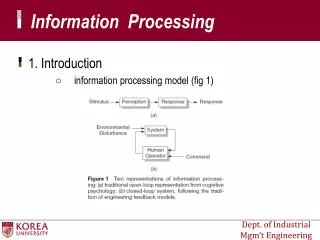
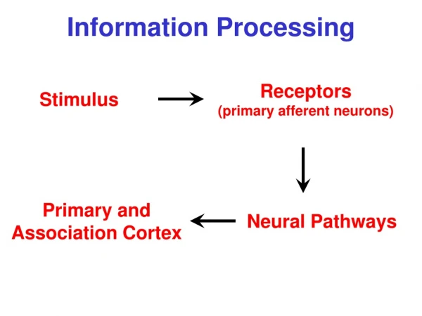
What is Optical Information Processing? It is the use of light to process information. Why use light anyways? 1) Information travels at the speed of light. Limitations are only due to the slow speed of the Spatial Light Modulators. 2) Parallel processing if arrays are used. 3) Immune to outside Electro-magnetic interference and crosstalk between waveguides and fiberoptic cables. 4) No short circuiting problems. Light by itself does not carry any information unless it is modulated by some means. Frequency, Polarization, Amplitude or the direct current of a semiconductor laser itself can be modulated, so that it may represent some form of information. Once modulated, light can then be used for performing arithmetic operations for analog or digital information processing.
I. Fourier Transform Property of a Lens. (FOURIER OPTICS) In a nutshell, the FT provides information on the frequency content of the signal. Coherent Laser Light illuminates the transparency at different path lengths. Each path diffracts through the lens at a different OPL causing phase shifts related to each path. All these paths from each element of the transparency add up at the back focal plane, thereby forming a diffraction pattern which is the Fourier Transform (FT) of the input transparency. The back focal plane is hence known as the Fourier Plane of the lens.
When the FT pattern goes through the second lens, it performs another FT and that is the restored image. Hence, FT of the FT is called the Convolution and the second lens is called the Convolver. This is a completely reversible operation so if the FT of the signal is completely known, the signal is also completely determined. A sinusoidal pattern appears, this indicates that points along the axis represent spatial frequency components in an image. How is it parallel processing? The input transparency is 2-Dimensional. Hence all illuminated elements of the transparency form an image on the focal plane simultaneously.
II. Analog Information Processing Real Images are Analog in nature. By using Fourier Optics we can perform arithmetic functions: Multiplication- The output image is nothing but multiplication of all individual paths that make up the image. Addition- If a hologram is used as the input transparency, then sum and product terms are present in the equation of a hologram. These are the signal and reference signals used to form a Hologram. Hence these addition and multiplication functions can be performed. Division- An inverted or reciprocal of the input image is used in the second focal plane. This performs a division of the input image. Subtraction- When an image is formed due to constructive (addition) and destructive (subtraction) interference produced due to different path lengths and related phase shifts.
What does Fourier Optics accomplish? We can perform Convolution, Cross-correlation, Autocorrelation and Matched Filtering which are all properties of a Fourier Transform. Cross-correlation is a useful technique for determining the similarity between two objects. In effect, what cross-correlation does is compare an object point by point with an input pattern.
Fig. Fourier Transform and Correlation Property in Pattern Recognition
Light Deflectors used for processing of Vectors Matrix Multiplication.
The Main Element of Digital Optical Information Processing. The Transistor – It is basically an ON-OFF switch. Which gives a value of ‘1’ or ‘0’ for ON or OFF. Figure 7 NPN Transistor-Conducting The language of computers - ‘0’ or ‘1’ are two binary digits used in digital computers and digital arithmetic. By using Boolean Logic Algebra, we can form any Logic gate for the purpose of performing mathematical operations.
SPATIAL LIGHT MODULATORS and OPTICAL SWITCHES Property used for the modulation of light. Birefringence – It is the property of a solid crystal or liquid exhibiting two indices of refraction in the presence of an electric or acoustic field. Due to the change in the refraction index, the speed of light changes in the solid or liquid. Hence the light beam either passes or does not pass depending on index of refraction.
Birefringence is also called double refraction because when the light enters the crystal, it is refracted into two different directions. Many crystalline materials exhibit birefringence naturally, without application of any voltage. The birefringence is present all the time. Examples of such crystals are quartz and calcite.
Birefringence can also be induced by the following means: 1) Electro-Optic (Electric current), 2) Acousto-Optic (Ultrasound), Electro-Optic Modulator There are also a number of crystals that are not birefringent naturally but in which application of a voltage induces birefringence. This is called the Electro-Optic effect in the crystal.
Fig 2. Schematic diagram of the operation of a modulator based on the electro-optic effect. In this configuration, the voltage is applied parallel to the direction of light propagation.
One uses transparent electrodes or electrodes with central apertures. When the voltage is applied parallel to the direction of light propagation This is called a longitudinal electro-optic modulator. In another form, metal electrodes are used on the sides of the crystal (which has a square cross section) and the voltage is perpendicular to the light propagation. This is called a transverse electro-optic modulator. Fig 2. Transverse Electro-Optic Modulator.
Application in Optical Information Processing - Right circular polarized can be used for ‘0’ and left circular polarized can be used for ‘1’. Or if it is a Liquid Crystal, then polarization will allow some light to pass when current is on and stop the light from passing when the current is off.
When the beams emerge from the crystal, the polarization of the combined single beam d depends on the accumulated phase difference. If the phase difference is one-half wavelength, the polarization is rotated by 90º from its original direction. This is done by using the Polarizer. This by itself does not change the intensity of the beam. But, with the analyzer, the transmission of the entire system varies, according to T = T0 sin2(p D nL/l ) --------------------------------------------- Equation 1 where T is the transmission, T0 the intrinsic transmission of the assembly, taking into account all the losses, D n the birefringence (that is, the difference in refractive index for the two polarizations), L the length of the crystal, l the wavelength of the light. The birefringence is an increasing function of the applied voltage, so that the transmission of the device will be an oscillatory function of applied voltage. The maximum transmission occurs when D n = l /2L -------------------------------------------------------Equation 2
This occurs at a voltage called the half-wave voltage, denoted V1/2. The half-wave voltage depends on the nature of the electro-optic material. The half-wave voltage for a particular material increases with the wavelength. Thus, in the infrared the required voltage is higher than in the visible. This factor can limit the application of electro-optic modulators in the infrared. Fig. 3Transmission of an electro-optic device as a function of applied voltage. V1/2 denotes the half-wave voltage.
Acousto-Optic Modulators The Elasto-optic properties of the medium respond to the acoustic wave so as to produce a periodic variation of the index of refraction. A light beam incident on this disturbance is partially deflected in much the same way that light is deflected by a diffraction grating. The operation is shown in Figure 6. The alternate compressions and rarefactions associated with the sound wave form a grating that diffracts the incident light beam. No light is deflected unless the acoustic wave is present.
Fig. 6 Diagram showing the principles of operation of an acousto-optic light-beam modulator or deflector.
The transmission T of an acousto-optic modulator is T = T0 sin2(p (M2PL/2H)0.5/l cos Q )-------------------------- Equation 4 where P ----------is the acoustic power supplied to the medium, l ------------is the wavelength, L------------ is the length of the medium (length of the region in which the light wave interacts with the acoustic wave), H------------------- is the width of the medium (width across which the sound wave travels), T0 ------------------- inherent transmission is a function of reflective and absorptive losses in the device. The quantity M2 is a figure of merit or diffraction efficiency, a material parameter that indicates the suitability of a particular material for this application. It is defined by M2 = n6p2/r v3 --------------------------------------------------- Equation 5 Where p is the photoelastic constant of the material, r is its density, and v is the velocity of sound in the material.
The Bragg angle Q is defined as the angle the beam makes with the reflecting waves. It is given by: sin Q = l/2nL......................................................................Equation where n is the index of refraction of the material, l is the optical wavelength and L is the acoustic wavelength. Hence AO modulates the intensities as well as deflects the beam. The diffracted output signal has intensities dependent upon the index of refraction and the frequency of light. Its application in Optical Information Processing – Different intensities e.g dark or light can be used to represent a ‘0’ or ‘1’. Light deflection properties are used in array arithmetic e.g Vector Matrix Multiplication as seen before.
Light Deflectors used for processing of Vectors Matrix Multiplication.
Advantages of Acousto-optic switches Using an acoustic wave containing M frequencies, the incoming beam can be routed simultaneously over M directions, and the Acousto-optic switch can be used to route information carried by one or more optical beams to one or more outputs. Disadvantages of Acousto-optic switches Limited switching time due to the time it takes for the acousto-optic signal to propagate across the length of the device … remember the speed of sound is much less than that of light!
(1) A + B = B + A Commutative law for addition (2) A + (B + C) = (A + B) + C Associative law of addition (3) A + 0 = A 0 is the zero matrix (4) A + (-A) = 0 -A = (-aij) (5) A(BC) = (AB)C Associative law for multiplication (6) ImA = A;AIn = A (if A is m × n) the identity matrix behaves as a unit (7) A(B + C) = AB + AC(A + B)C = AC + BC Distributive law (8) (a + b)C = aC + bC a, b scalars (9) a(B + C) = aB + aC (10) a(BC) = (aB)C = B(aC)
AND Gate A NOR Gate A A OR Gate NAND Gate A B B B B Q Q Q Q 0 0 0 0 0 0 0 0 0 1 0 1 0 0 0 0 1 1 1 1 1 0 0 1 1 1 1 1 0 0 0 0 1 1 0 0 1 1 1 1 1 1 1 1 0 1 1 0
Fabry-Perot Etalon Optical Transistors using Nonlinear Crystals We can implement a full adder using a single Etalon by controlling the intensity of the input signals and using the transmission and reflection signals of the Etalon. A nonlinear material such as Lithium niobate (LiNbO3) is used in the Etalon cavity. Much faster than a Silicon transistor with switching times 10 power –15 seconds. The Etalon can be used as an ON-OFF switch. Hence the laser intensity of the output pulses can be modified by this on-off switch and can represent a ‘0’ or ‘1’. Hence, to implement a logic function you simply apply optical signals of an appropriate intensity to the input of the device.
For an Optical Etalon Transistor Define the input signals A and B to be equal or greater than the switching threshold intensity (set to I the maximum output intensity, I, corresponding to a logic ‘1’), then For an OR Gate - if either A or B are high, the output will be high (I). For an AND Gate - if both A or B are high, the output will be high (I).
The condition for producing a maximum in transmission is given by Nl= – AD; where for example, is the optical path length between A and B in Figure 3. With the aid of some trigonometric relationships, the condition becomes: Nl= 2nd cos q l = The wavelength of the radiation in vacuum (or air). d = The separation of the reflecting surfaces. n = The index of refraction of the material between the reflecting surfaces. q = The angle of incidence, as shown in Figure N = An integer. The spacing Dl between maxima of transmission is: Dl = ,
Flip Flops The flip-flop I O (0,1) utilizes two logic gates in order to implement a 1-bit storage device or memory. Optical bistable devices can be used to produce single-element storage devices or RAM or ROM (Memory). One of the more interesting things that you can do with Boolean gates is to create memory with them. If you arrange the gates correctly, they will remember an input value. This simple concept is the basis of RAM (random access memory) in computers, and also makes it possible to create a wide variety of other useful circuits. Memory relies on a concept called feedback. That is, the output of a gate is fed back into the input. The simplest possible feedback circuit using two inverters is shown below:
If you follow the feedback path, you can see that if Q happens to be 1, it will always be 1. If it happens to be 0, it will always be 0. Since it's nice to be able to control the circuits we create, this one doesn't have much use -- but it does let you see how feedback works. It turns out that in "real" circuits, you can actually use this sort of simple inverter feedback approach. A more useful feedback circuit using two NAND gates is shown below:
A bistable optical device is simply a device that has two states in output power for all input power levels: a ‘1’ state for high input power levels and a ‘0’ state for small input power levels. Bistable optical devices requirenonlinear optical elements with feedback applied.
IV. Nonlinear Optics in Optical Information Processing Nonlinear materials belong to a group of non-centrosymmetric crystals. This means that the internal motion of electrons in an oscillating electric field is not symmetric. The material should furthermore exhibit a large index of refraction since there is, as a rule, a strong dependence of nonlinear optical properties on the refractive index.