Download

1 / 16
180 likes | 431 Views
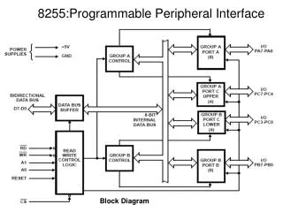
Programmable Peripheral Interface. Programmable Peripheral Interface (82C55). The 82C55 is a popular interfacing component, that can interface any TTL compatible I/O device to the microprocessor.

E N D
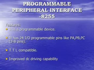
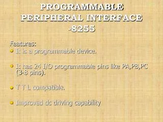
Programmable Peripheral Interface (82C55) • The 82C55 is a popular interfacing component, that can interface any TTL compatible I/O device to the microprocessor. • It is used to interface to the keyboard and a parallel printer port in PCs (usually as part of an integrated chipset). • Requires insertion of wait states if used with a microprocessor using higher that an 8 MHz clock. • PPI has 24 pins for I/O that are programmable in groups of 12 pins and has three distinct modes of operation. • In the PC, an 82C55 or its equivalent is decoded at I/O ports 60H-63H.
8255 Pins Description • PA0 - PA7: input, output, or bi-directional port • PB0 - PB7: input or output • PC0 - PC7: This 8 bit port can be all input or output. It can also be split into two parts, CU (PC4 - PC7) and CL (PC0 - PC3). Each can be used for input and output. • RD or WR (IOR and IOW of the system are connected) • RESET • A0, A1, and CS • CS selects the entire chip whereas A0 and A1 select the specific port
82C55: Mode 0 Operation • Mode 0 operation causes the 82C55 to function as a buffered input device or as a latched output device. • In example, both ports A and B are programmed as (mode 0) simple • latched output ports. • Port A provides the segment data inputs to display and port B provides a means of selecting one display position at a time. • Different values are displayed in each digit via fast time multiplexing. • The values for the resistors and the type of transistors used are determined using the current requirements
82C55: Mode 1 Strobed Input • Port A and/or port B function as latching input devices. External data is stored in the ports until the microprocessor is ready. • Port C used for control or handshaking signals (cannot be used for data). • Signal definitions for Mode 1 Strobed Input • INTR Interrupt request is an output that requests an interrupt • IFB Input buffer full is an output indicating that the input latch contain information • STB The strobe input loads data into the port latch on a 0-to-1 transition • INTE The interrupt enable signal is neither an input nor an output; it is an internal bit programmed via the PC4(port A) or PC2(port B) bits. • PC7,PC6 The port C pins 7 and 6 are general-purpose I/O pins that are available for any purpose.
82C55: Mode 1 Strobed Output • Similar to Mode 0 output operation, except that handshaking signals are provided using port C. • Signal Definitions for Mode 1 Strobed Output • OBF Output buffer full is an output that goes low when data is latched in either port A or port B. Goes low on ACK. • ACK The acknowledge signal causes the OBF pin to return to 0.This is a response from an external device. • INTR Interrupt request is an output that requests an interrupt • INTE The interrupt enable signal is neither an input nor an output; it is an internal bit programmed via the PC6(port A) or PC2(port B) bits. • PC5,PC4 The port C pins 5 and 4 are general-purpose I/O pins that are available for any purpose.