Download
1 / 1
10 likes | 91 Views
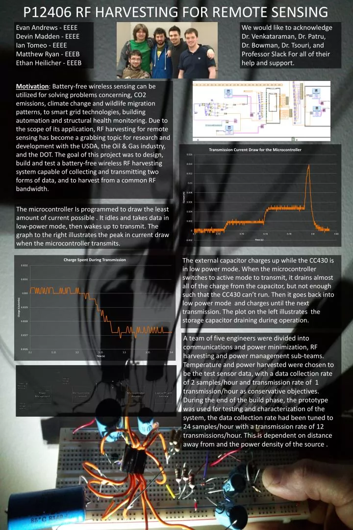
Evan Andrews - EEEE Devin Madden - EEEE Ian Tomeo - EEEE Matthew Ryan - EEEB Ethan Heilicher - EEEB. We would like to acknowledge Dr. Venkataraman , Dr. Patru , Dr. Bowman, Dr. Tsouri , and Professor Slack For all of their help and support.

E N D
Evan Andrews - EEEE Devin Madden - EEEE Ian Tomeo - EEEE Matthew Ryan - EEEB Ethan Heilicher - EEEB We would like to acknowledge Dr. Venkataraman, Dr. Patru, Dr. Bowman, Dr. Tsouri, and Professor Slack For all of their help and support. Motivation:Battery-free wireless sensing can be utilized for solving problems concerning, CO2 emissions, climate change and wildlife migration patterns, to smart grid technologies, building automation and structural health monitoring. Due to the scope of its application, RF harvesting for remote sensing has become a grabbing topic for research and development with the USDA, the Oil & Gas industry, and the DOT. The goal of this project was to design, build and test a battery-free wireless RF harvesting system capable of collecting and transmitting two forms of data, and to harvest from a common RF bandwidth. P12406 RF HARVESTING FOR REMOTE SENSING The microcontroller Is programmed to draw the least amount of current possible . It idles and takes data in low-power mode, then wakes up to transmit. The graph to the right illustrates the peak in current draw when the microcontroller transmits. The external capacitor charges up while the CC430 is in low power mode. When the microcontroller switches to active mode to transmit, it drains almost all of the charge from the capacitor, but not enough such that the CC430 can’t run. Then it goes back into low power mode and charges until the next transmission. The plot on the left illustrates the storage capacitor draining during operation. A team of five engineers were divided into communications and power minimization, RF harvesting and power management sub-teams. Temperature and power harvested were chosen to be the test sensor data, with a data collection rate of 2 samples/hour and transmission rate of 1 transmission/hour as conservative objectives. During the end of the build phase, the prototype was used for testing and characterization of the system, the data collection rate had been tuned to 24 samples/hour with a transmission rate of 12 transmissions/hour. This is dependent on distance away from and the power density of the source .