Download

1 / 34
410 likes | 1.53k Views
Introduction to Radar. Shaohua Li Graduate Student Department of Electrical and Computer Engineering. Functions of Radar. RADAR is a method of using electromagnetic waves to remote-sense the position, velocity and identifying characteristics of targets. History of Radar.

E N D
Introduction to Radar Shaohua Li Graduate Student Department of Electrical and Computer Engineering
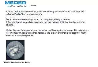
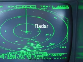
Functions of Radar • RADAR is a method of using electromagnetic waves to remote-sense the position, velocity and identifying characteristics of targets.
History of Radar • Radar was developed for military purposes during W. W. II. • The British and US Military used radar to locate ships and airplanes.
History of Radar • During the war, radar operators found annoying blips continually appearing on the radar screen. Scientists had not known that radar would be sensitive enough to detect precipitations. • Today, radar is an essential tool for predicting and analyzing the weather.
Weather Radar • Weather Surveillance Radar, designed in 1957. It became the primary radar for the weather service for nearly 40 years.
Weather Radar NSSL's first Doppler Weather Radar located in Norman, Oklahoma. 1970's research using this radar led to NWS NEXRAD WSR-88D radar network.
The expensive radar equipment is protected by the sphere shaped cover. On the inside it looks similar to this:
Two Basic Radar Types • Pulse Transmission • Continuous Wave
Pulse Diagram PRF Resting Time Carrier Wave PW
Pulse Radar Components Synchronizer Transmitter RF Out Power Supply Duplexer ANT. Echo In Display Unit Receiver Antenna Control
Pulse Transmission • Pulse Repetition Time (PRT=1/PRF) • Pulse Width (PW) • Length or duration of a given pulse • PRT is time from beginning of one pulse to the beginning of the next • PRF is frequency at which consecutive pulses are transmitted. • PW can determine the radar’s minimum range resolution. • PRF can determine the radar’s maximum detection range.
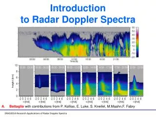
Continuous Wave Radar • Employs continual RADAR transmission • Relies on the “DOPPLER EFFECT”
Motion Away Echo Frequency Decreases Motion Towards Echo Frequency Increases Doppler Frequency Shifts
Continuous Wave Radar Components Transmitter Antenna CW RF Oscillator OUT IN Discriminator Mixer AMP Antenna Indicator
Pulse Echo Single Antenna Gives Range & Alt. Susceptible To Jamming Physical Range Determined By PW and PRF. Continuous Wave Requires 2 Antennae No Range or Alt. Info High SNR More Difficult to Jam But Easily Deceived Amp can be tuned to look for expected frequencies Pulse Vs. Continuous Wave
Classification by Primary Radar Mission • Search radars and modes • Surface search • Air search • Two-dimensional search radars • Three-dimensional search radars • Tracking radars and modes • Track-while-scan
AN/TPS-43 The AN/TPS-43 radar system, with a 200 mile range, was the only Air Force tactical ground based long range search and warning radar for nearly two decades. Most of the AN/TPS-43 radars are being modified to the AN/TPS-75 configuration. 3-D Air Search Radar
Tracking Radar • Tracking radars dwell on individual targets and follow their motion in azimuth, elevation,range and Doppler. • Most tracking radars can follow only a single target. • A few radars can track multiple targets simultaneously. An electronically steered array antenna is used so that beam positions can be moved quickly from one target to another.
AN/APG-66 in the F-16 http://www.tpub.com/neets/book18/79j.htm
Types of Antenna Introducing two types of antenna • reflector mirror antenna • array antenna
Parabolic Reflector Basic paraboloid reflector; Truncated paraboloid;Orange-peel paraboloid;Cylindrical paraboloid
Array Antenna • An array antenna is composed of multiple element arrays for example, linear array, area array or nonformal array. The element antennas are half-wavelength dipoles, microstrip patches and wave guide slot. The advantages of array antenna are to enable beam scanning without changing the looking angle of each array antenna and to generate an appropriate beam shaping by selective excitation of current distribution of each element.
Edgewall Slot Array-AN/APY-2 on E-3D Aircraft The E-3 Sentry is an airborne warning and control system (AWACS) aircraft that provides all-weather surveillance, command, control and communications needed by commanders of U.S. and NATO air defense forces. As proven in Desert Storm, it is the premier air battle command and control aircraft in the world today.
AN/FPS-115 PAVE PAWS Early Warning Radar Array Antenna PAWS stands for Phased Array Warning System. The radar is used primarily to detect and track sea-launched and intercontinental ballistic missiles. It can search over long distance(to 5000 km or more). Each system has two array faces 72.5 feet in diameter with 2677 element positions. To provide surveillance across the horizon, the building is constructed in the shape of a triangle. The two building faces supporting the arrays, each covering 120 degrees, will monitor 240 degrees of azimuth.
Radar Performance and Frequency Bands • Bandwidth The bandwidth determines the range resolution and frequency agility capabilities of the radar. • Antenna For a given gain, low frequency antennas are larger than high frequency. Low frequency are favored for long-range search applications, because of the larger effective area associated with a given gain, allowing more effective capture of echoes. • Transmitter In general, more radio frequency power can be produced at low frequency than at high. • Receiver There is no clear choice between high and low frequencies. • Propagation The attenuation at high frequency is dramatic. A given raindrop has over three orders of magnitude more scattering cross-section at X-band(10 GHz) than at L-band(1.3 GHz), producing far more clutter and signal at the higher frequency. • Targets If the wavelength is long compared to the target extent, targets are Rayleigh scatterers, and have small, non-fluctuating RCS. • Summary In general, the longer the range at which the radar must detect targets, the lower the frequency of the radar.
Reference • www.fas.org/man/dod-01/sys/ac/equip/ • http://www.tpub.com/neets/book11/46a.htm • http://www.tpub.com/neets/book18/79j.htm • etc.