Download
1 / 34
350 likes | 574 Views
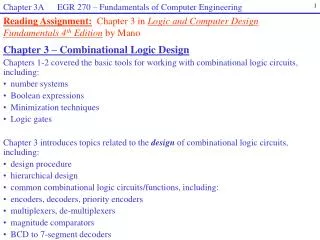
Combinational Design, Part 3. Chapter 4 (Sections 3, 4, 5). Topics. Common Logic Functions Decoders Encoders Multiplexers. Value Fixing, Transferring, Inverting. Only 4 possible functions of one variable 2 constant 1 xfer 1 invert. Enable. Enable is a common input to logic functions

E N D
Combinational Design,Part 3 Chapter 4 (Sections 3, 4, 5)
Topics • Common Logic Functions • Decoders • Encoders • Multiplexers
Value Fixing, Transferring, Inverting • Only 4 possible functions of one variable • 2 constant • 1 xfer • 1 invert
Enable • Enable is a common input to logic functions • See it in memories, and today’s blocks
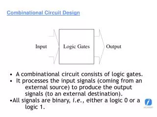
Decoders • Discrete quantities are represented by binary codes. • n-bit binary code is capable of representing 2n distinct elements of coded information. • Decoding is the conversion of an n-bit code to an m-bit output code with n<= m <= 2nsuch that each valid input code produces a unique output code. • Decoding is performed by a decoder. • The decoder may have unused bit combinations on its inputs for which no corresponding m-bit code appear on the output
1-to-2 Line Decoder Decoders • Typically n inputs and 2n outputs • The purpose is to generate 2n or fewer minterms. • Drives high the output corresponding to binary code of input
Note that the 2-to-4 decoder is made of 2 (1-to-2 ) line decoders and 4 AND gates 2-to-4 Line Decoder
Truth Table, 3-to-8 Decoder • Notice they are minterms
Schematic 8 3-inputAND gates are needed
Alternative Design: Multi-Level 3-to-8 Level 1 1-to-2 Line decoder Level 2 Build 2-to-4 Line decoder using level 1 decoders with 4 2-input AND gates Level 3: Build 3-to-8 Line decoder using level 1, level 2 decoders with 8 2-input AND gates
…. = C0B0 B0, B1, B2, …, B7 D7= C0B7 … D8= C1B0 D15= C1B7 C0, C1, C2, …, C7 = C7B7 Multi-Level 6-to-64 Decoder …. ...
Uses for Decoders • Binary number might serve to select some operation • Computer operation codes are encoded • Decoder lines might select add operation, or subtract operation, or multiply operation, etc. • Memory address lines
Variations • At right • Enable not • Inverted outputs
74139 74139Two 2-to-4 Line Decoders; Enable Not ; Inverted Outputs
Encoder • Encoder is the opposite of decoder • 2n inputs • or less – 10 inputs in BCD: I0, I1, I2, I3, …, I9 • n outputs • 4 output line for BCD code
Inputs are Minterms • Can OR them together appropriately • A0 = D1 + D3 + D5 + D7 • A1= D2 + D3 + D6 + D7 • A2= D4 + D5 + D6 + D7
What’s the Problem? • What if D3 and D6 both high? • Simple OR circuit will set A (the output) to 7
Priority Encoder • Chooses one with highest priority • i.e. produce the code of the input with the highest priority • Largest number, usually • Note “don’t cares” What if all inputs are zero?
Need Another Output • A “Valid” output
Figure 4-12 Logic Diagram of a 4-Input Priority Encoder Valid is OR of inputs
K Map for A0 • X on an input means the circuit must generate the specified output value for both input possibilities: 0, 1
74153 Multiplexer (or Mux) • Selects one of a set of inputs to pass on to output • Binary control code, n lines • Choose from 2n inputs • Useful for choosing from sets of data • Memory or register to ALU • Very common
4-to-1-Line Multiplexer Logic: Four Input Mux
A Single Bit 4-to-1 Line Multiplexer Logic is a Decoder Plus4 X 2-Input AND gates feeding an OR gate
Quad 2-to-1 Mux • Select one of two sets of lines A & B; each set has 4 lines • Practical use: Select a whole 64-bit data bus from one of many sources
Gate input count is 18 Three-State Implementation
Gate input count is 14 Binary Tree Style
1-to-4-Line Demultiplexer Demultiplexer • Takes one input • Out to one of 2n possible outputs
Demux is a Decoder • With an enable