Download
1 / 56
560 likes | 750 Views
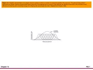
Chapter 12. Data Converters. Data Converters: Basic Concepts. Analog signals are continuous, with infinite values in a given range. Digital signals have discrete values such as on/off or 0/1. Limitations of analog signals Analog signals pick up noise as they are being amplified.

E N D
Chapter 12 Data Converters
Data Converters: Basic Concepts • Analog signals are continuous, with infinite values in a given range. • Digital signals have discrete values such as on/off or 0/1. • Limitations of analog signals • Analog signals pick up noise as they are being amplified. • Analog signals are difficult to store. • Analog systems are more expensive in relation to digital systems.
Data Converters: Basic Concepts • Advantages of digital systems (signals) • Noise can be reduced by converting analog signals in 0s and 1s. • Binary signals of 0s/1s can be easily stored in memory. • Technology for fabricating digital systems has become so advanced that they can be produced at low cost. • The major limitation of a digital system is how accurately it represents the analog signals after conversion.
Embedded System • A typical system that converts signals from analog to digital and back to analog includes: • A transducer that converts non-electrical signals into electrical signals • An A/D converter that converts analog signals into digital signals • A digital processor that processes digital data (signals) • A D/A converter that converts digital signals into equivalent analog signals • A transducer that converts electrical signals into real life non-electrical signals (sound, pressure, and video) So, how does A/D Converter works?
A/D Converter • In order to change an analog signal to digital, the input analog signal is sampled at a high rate of speed. • The amplitude at each of those sampled moments is converted into a number equivalent – this is called quantization. • These numbers are simply the combinations of the 0s and 1s used in computer language – this called encoding. http://www.cybercollege.com/tvp008.htm
A/D Conversion – Pulse Code Modulation/Demodulation Modulation Demodulation PCM Signal
Analog-to-Digital 7/8 • A simple hypothetical A/D converter circuit with one analog input signal and three digital output lines with eight possible binary combinations: 000 to 111 • Shows the graph of digital output for FS V analog input • The following points can be summarized in the above process: • Maximum value this quantization process reaches is 7/8 V for a 1 V analog signal; includes 1/8 V an inherent error • 1/8 V (an inherent error) is also equal to the value of the Least Significant Bit (LSB) = 001. • Resolution of a converter is defined in terms of the number of discrete values it can produce; also expressed in the number of bits used for conversion or as 1/2n where n =number of bits • The value of the most significant bit (MSB) -100- is equal to ½ the voltage of the full-scale value of 1 V. • The value of the largest digital number 111 is equal to full-scale value minus the value of the LSB. • The quantization error can be reduced or the resolution can be improved by increasing the number of bits used for the conversion
A little Detour: Opamp Review • http://www.engin.brown.edu/courses/en123/Lectures/DAconv.htm • http://www.seas.upenn.edu/~ese206/labs/adc206/adc206.html
Opamps Ideal opamps Infinite BW Infinite voltage gain Infinite input impedance Zero output impedance Practical opamps wide BW Very high voltage gain Very high input impedance Very low output impedance http://www.chem.uoa.gr/Applets/AppletOpAmps/Appl_OpAmps2.html
Closed Loop Frequency Response Non-inverting Source is connected to the non-inverting input Feedback is connected to the inverting input If Rf and Ri are zero, then unity feedback used for buffering Av=1+Rf/Ri Inverting Feedback and source are connected to the inverting input Av=-Rf/Ri
Comparators • Determines which input is larger • A small difference between inputs results maximum output voltage (high gain) • Zero-level detection • Non-zero-level detection Max and minimum
Example Vref = Vin(max).R2/(R1+R2)=1.63 V
A/D Conversion - Types • Can be classified in four groups: • Integrator: • Charges a capacitor for a given amount of time using the analog signal. • It discharges back to zero with a known voltage and the counter provides the value of the unknown signal. • Provides slow conversion but low noise. • Often used in monitoring devices (e.g., voltmeters) • Flash: uses multiple comparators in parallel. • The known signal is connected to one side of the comparator and the analog signal to be converted to the other side of the comparator. • The output of the comparators provides the digital value. • This is a high-speed, high cost converter.
A/D Conversion • Flash Converter • The circuit consists of 4 comparators whose inverting inputs are connected to a voltage divider. • A comparator is basically an operational amplifier used without feedback. • The outputs of the comparators correspond to a digital word. • When the input rises above Vn1 , the first comparator will switch to a high output voltage causing the LED to light up, indicating a (0001). • For larger input voltages the output of other comparators will switch high as well. For large input voltages (above Vn3) all comparators will be high corresponding to (1111) digital output.
A/D Conversion • Successive approximation: Includes a D/A (digital to analog) converter and a comparator. An internal analog signal is generated by turning on successive bits in the D/A converter. • Counter: Similar to a successive approximation converter except that the internal analog signal is generated by a counter starting at zero and feeding it to the D/A converter.
Successive Approximation A/D Converter Circuit • The SAR (successive approximation register) begins by turning on the MSB Bit7. • Vo of the D/A converter is compared with the analog input voltage Vin in the comparator. • If analog voltage is less than the digital voltage, Bit7 is turned off and Bit6 is turned on. • If analog voltage is greater than the digital voltage, Bit7 is kept on and Bit6 is turned on. • The process of turning bit on/off is continued until Bit0. • Now the 8-bit input to the D/A converter represents the digital equivalent of the analog signal Vin. Display Bit 7 is set: b7=1 If Va < Vd b7=0; b6=1 If Va > Vd b7=1; b6=1 ….. If Va < Vd b7=0; …b0=1 If Va > Vd b7=1; … b0=1 Done
Sample and Hold Circuit • If the input voltage to an A/D converter is variable, the digital output is likely to be unreliable and unstable. Therefore, the varying voltage source is connected to the ADC through a sample and hold circuit. • Basic Operation: • When the switch is connected, it samples the input voltage. ADG1211 Switch • When the switch is open, it holds the sampled voltage by charging the capacitor. • Acquisition time: time to charge the capacitor after the switch is open and settle the output. • Conversion time: total time needed from the start of a conversion (turning on the MSB in the SAR) until the end of the conversion (turning on/off Bit0 in the SAR) - TAD: conversion time per bit.
A/D Examples • Example 1 • Assumes the input analog voltage is changing between 0-5 V. • Using a 3-bit A/D converter draw the output as the input signal ramps from 0 to 5V. • Calculate the resolution. • What is the maximum possible voltage out? (this is called the full-scale output) • If the output is 1000 0000, what is the input? • Example 2 • Assumes the input analog voltage is changing between -5 to 5 V; using a 10-bit A/D converter. • Calculate the number of quantization levels. • Calculate the voltage resolution.
A/D Examples • Example 1 • Assumes the input analog voltage is changing between 0-5 V. • Using a 3-bit A/D converter draw the output as the input signal ramps from 0 to 5V. • Calculate the resolution. 1 / 2^8 = 19.53 mV • What is the maximum possible voltage out? (this is called the full-scale output) 5- Resolution • If the output is 1000 0000, what is the input? MaxVolt / 2 = 2.5 • Example 2 • Assumes the input analog voltage is changing between -5 to 5 V; using a 10-bit A/D converter. • Calculate the number of quantization levels. 2^10 • Calculate the voltage resolution. 5-(-5)/1024=9.76 mV
PIC18F4520 Analog-to-Digital (A/D) Converter Module (1 of 3) • The PIC184520 microcontroller includes: • 10-bit A/D converter • 13 channels AN0 – AN12 • Three control registers • ADCON0, ADCON1, and ADCON2
PIC18F4520 Analog-to-Digital (A/D) Converter Module (2 of 3) • ADCON0, ADCON1, and ADCON2 • ADRESH and ADRESL ADCON0 ADRESH/L 16-bit VCFG0 VCFG1
PIC18F4520 Analog-to-Digital (A/D) Converter Module (3 of 3) • Three control registers are used to: • Set up the I/O pins for analog signals from ports A, B, and E that are used as inputs for A/D conversion. RA5 • Select a channel: AN4 • Set up pins RA2 and RA3 to connect external VREF + and VREF - if specified in the control register ADCON1. • Select an oscillator frequency divider through the control register ADCON2. • Select an acquisition time through the control register ADCON2. If the input is 0-1V Vin=[0-1]: Option1: Vref+ & Vref- 1V & GND Option 2: Shift Vin to Vin’= Vin=[0-Vcc] and then Vref+ & Vref- Vcc & GND
Primary function of the ADCON0 register: Select a channel for input analog signal Start a conversion Indicate the end of the conversion Bit1 is set to start the conversion, and at the end of the conversion this bit is reset. A/D Control Register0 (ADCON0)
ADCON1 is primarily used to set up the I/O pins either for analog signal or for digital signals (see Table 12.2) and select VREF voltages (see Table 12.1). A to D Control Register1 (ADCON1)
A to D Control Register2 (ADCON2) (1 of 2) • Used to: • Select an acquisition time and clock frequency • Right or left justify output reading • The output reading, after a conversion, is stored in the 16-bit register ADRESH and ADRESL. However, this is a 10-bit A/D converter leaving six bit positions unused. • Bit7 ADFM enables the user either to right justify or left justify the 16-bit reading leaving the unused positions as 0s.
Example 12.3 • Interfacing a 10 k Pot
Example: • What are the right questions? • Where is the input connected to? • Which channel is connected to the A/D • Using external or internal clock • What is the Vref? • What is the minimum sampling time? • What is the acquisition time?
Example • Assumptions • Use RA0 on the demo board. • Use external oscillator • Assuming conversion time (TAD) is 4 usec, what is the clock frequency requirement (ADCON2) • Assume acquisition time is 48 usec. What will be the acquisition time setting? • Write the program • Set up the following registers properly: • ADCON0, ADCON1, ADCON2.
Example Basic calculations: Fosc = 4MHz Tconv_time = TAD = 4usec = 1/(Fosc/x) x=16, hence, select Fosc/16 Taqu-time = 48usec = y. Tconv_time y=12, hence select 12.TAD Setting: ADCON0 = 00 000 01 ADCON1 = 00 00 00 11 ADCON2 = 10 101 101
Interfacing a Temperature Sensor (1 of 7) • Temperature sensor • Transducer that converts temperature into an analog electrical signal • Many are available as integrated circuits, and their outputs (voltage or current) are, in general, linearly proportional to the temperature • However, output voltage ranges of these transducers may not be ideally suited to reference voltages of A/D converters • Therefore, it is necessary to scale the output of a transducer to range of the reference voltages of an A/D converter • Scaling may require amplification or shifting of voltages at a different level
Interfacing a Temperature Sensor (2 of 7) • Temperature Sensor • Interface the National Semiconductor LM34 temperature sensor to channel 0 (AN0) of the A/D converter module as shown in Figure 12.11. • Assume the output voltage of LM34 for the temperature range from 0ºF to 100ºF is properly scaled to 0 to +5 V. • Write instructions to start a conversion, read the digital reading at the end of the conversion, calculate the equivalent temperature reading in degrees Fahrenheit, convert it into BCD, and store the reading in ASCII code to the accuracy of one decimal point. • The expected range of temperatures is 0ºF to 99.9ºF.
Interfacing a Temperature Sensor (3 of 7) http://users.ipfw.edu/broberg/documents/LM34.pdf
Interfacing a Temperature Sensor (4 of 7) • Hardware • Temperature transducer LM34 • Three-terminal integrated circuit device that can operate in the +5 V to +30 V power supply range • Outputs 10 mV/ºF linearly • For the temperature range from 0ºF to +99.9ºF; the output voltage range is 0 to 1 V (rounded off to 100ºF).
Interfacing a Temperature Sensor (5 of 7) • Scaling circuit • To get the full dynamic range of the A/D conversion for the output voltage range 0 to 1V of LM34: • We can connect +VREF to +1 V or • Scale the output voltage +1V to the voltage of the power supply +5 V • This scaling enables us to connect PIC18 power supply VDD as voltage reference +VREF and ground Vss as –VREF. 1 V 5 V Non-inverting opamp: Av = 1 + Rf/Ri 0 V 0 V
Remember …. Vref = Vin(max).R2/(R1+R2)=1.63 V
Non-Inverting Voltage Level Shifter • Equations: • A = (R4/R1) x (R1+R2)/(R3+R4) • If R1= R3, and R2=R4, then A= (R4/R1) • We want to convert a 10Vpp signal to a 3.3V signal so the gain should be 1/3. We can choose R4 to be 33K and R1 to be 100K. • We need to choose the positive offset such that the signal is centered at 1.6V. • The gain off the offset voltage is: • Aoffset= (R2+R1)/R1 x R3/(R3+R4) = R3/R1. • For the previous resistor values, the gain is 1 since R3=R1, and so we use an offset voltage of 1.6V.
Interfacing a Temperature Sensor (6 of 7) • Temperature calculations • A/D converter has 10-bit resolution • For temperature range 0ºF to +100ºF, the digital output should be divided into 1023 steps (0 to 3FFH). • Therefore, the digital value per degrees Fahrenheit is 10.23 (1023/100 = 10.2310). • To obtain temperature reading from a digital reading of the A/D converter, the digital reading must be divided by the factor of 10.23.
Interfacing a Temperature Sensor (7 of 7) • Software modules • Program should be divided into the following: • Setup all analog ports and channels • Assume TAD = 12 and Fosc / 16 • Initialize A/D module (acquire analog input) • Start a conversion and read the digital reading at the end of the conversion. • Multiply the temperature reading by 10 • Divide the 16-bit result by 102 QUO and REM This is the equivalent temperature reading. • Convert the result in BCD. • Convert the BCD numbers in ASCII code.
Digital to Analog (D/A, DAC, or D-to-A) Conversion • Converting discrete signals into discrete analog values that represent the magnitude of the input signal compared to a standard or reference voltage • The output of the DAC is discrete analog steps. • By increasing the resolution (number of bits), the step size is reduced, and the output approximates a continuous analog signal.
Analysis of a Ladder Network A resistive ladder network is a special type of series-parallel circuit. One form of ladder network is commonly used to scale down voltages to certain weighted values for digital-to-analog conversion Called R/2R Ladder Network To find total resistance of a ladder network, start at the point farthest from the source and reduce the resistance in steps.
The R/R2 Ladder Network Only Input 4 is HIGH Only Input 3 is HIGH Used for Digital-to-analog converter!
Examining Digital-to-Analog Conversion For Extra credit: Change the circuit to generate this output:
Digital to Analog Conversion • The resolution of a DAC is defined in terms of bits—the same way as in ADC. • The values of LSB, MSB, and full-scale voltages calculated the same way as in the ADC. • The largest input signal 111 is equivalent of 7/8 of the full-scale analog value.
D/A Converter Circuits (1 of 4) • Can be designed using an operational amplifier and appropriate combination of resistors • Resistors connected to data bits are in binary weighted proportion, and each is twice the value of the previous one. • Each input signal can be connected to the op amp by turning on its switch to the reference voltage that represents logic 1. • If the switch is off, the input signal is logic 0.
3-bit D/A Converter Circuit R/2R Ladder Network for D/A Converter D/A Converter Circuits (2 of 4) The transfer function of the summing amplifier : vo = -(v1/R1 + v2/R2 + … + vn/Rn)Rf Thus if all input resistors are equal, the output is a scaled sum of all inputs. If they are different, the output is a weighted linear sum of all inputs. Summing amplifier
D/A Converter Circuits • If the reference voltage is 1 V, and if all switches are connected, the output current can be calculated as follows: • Output voltage Note that the output will be inverted!
D/A Converters as Integrated Circuits • D/A converters are available commercially as integrated circuits • Can be classified in three categories. • Current output, voltage output, and multiplying type • Current output DAC provides the current IOas output signal • Voltage output D/A converts IO into voltage internally by using an op amp and provides the voltage as output signal • In multiplying DAC, the output is product of the input voltage and the reference source VREF. • Conceptually, all three types are similar
Example 12.4 Vref = 5V • What will be the analog equivalent of 1001 0001?