Download
1 / 30
300 likes | 413 Views
Electron [and ion] beam studies of magnetic nanostructures. John Chapman, Department of Physics & Astronomy, University of Glasgow. Synopsis Domain wall structures Investigation by Lorentz microscopy Domain wall widths in soft films

E N D
Electron [and ion] beam studies of magnetic nanostructures John Chapman, Department of Physics & Astronomy, University of Glasgow Synopsis Domain wall structures Investigation by Lorentz microscopy Domain wall widths in soft films Magnetisation reversal processes in soft high-moment films Single layer films The effects of lamination – desirable and otherwise! Magnetisation reversal processes in magnetic elements Vortices The role and elimination of metastable states Domain wall traps Notches (constrictions) in magnetic wires [Domain wall modification by ion irradiation]
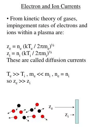
M + - + - + - M M M M M M M M + - - + + - - + + - - + M Schematics of 180 domain wall structures Schematic of Bloch wall Schematic of cross-tie wall Schematic of Neel wall
3.8 Oe 15mm 20 nm permalloy film; H parallel to hard axis Fresnel imaging mode
probe-forming aperture scan coils Direction of induction mapped a B B o o specimen b L de-scan coils post- specimen lenses quadrant detector 5 m Differential phase contrast (DPC) imaging of a 180domain wall in a soft magnetic film
Experimental and theoretical domain wall widths in a 8 nm thick permalloy film 180° wall profiles in 8 nm thick permalloy: (a) as the free layer of a spin-valve and (b) as an isolated layer Fitting function: tanh(2x/w) SV isolated layer w (nm) 150 + 4 154 + 4 From Hubert (Phys. Stat. Sol. 38, 699, 1969) w (nm) 157
Synopsis Domain wall structures Investigation by Lorentz microscopy Domain wall widths in soft films Magnetisation reversal processes in soft high-moment films Single layer films The effects of lamination – desirable and otherwise! Magnetisation reversal processes in magnetic elements Vortices The role and elimination of metastable states Domain wall traps Notches (constrictions) in magnetic wires [Domain wall modification by ion irradiation]
High-moment CoFe multilayer films CoFe 10 nm ML4 NiFe 1 nm Al2O3 1.25 nm ML2 NiFe 1 nm Al2O3 1.5 nm CoFe 10 nm CoFe 22.5 nm CoFe 50 nm ML3 ML1 NiFe 1 nm NiFe 1 nm Al2O3 1.5 nm Laminating does not significantly change the total moment of the film but it changes the magnetisation curve and can lead to lower noise in devices.
CoFe 50 nm NiFe easy axis 3mm Ha +25Oe -13Oe -15Oe -14Oe -20Oe 3mm easy axis Ha +3Oe -8Oe -10Oe +10Oe +41Oe Easy and hard axis magnetisation reversals – ML1 Hc 15 Oe
easy axis Ha +45 Oe +8 Oe -41 Oe -2 Oe -4 Oe 2 mm 2 mm easy axis Ha +32 Oe +9 Oe -1 Oe -5 Oe -21 Oe Easy and hard axis magnetisation reversals – ML2 CoFe 22.5 nm NiFe Al2O3 Hc 5.3 Oe
Easy and hard axis reversal behaviour Hard axis Easy axis easy axis Domain wall easy axis Ha Ha Larger number of less mobile domain walls Small number of mobile domain walls
Néel walls in bilayer films - - + + - - + + 1 mm Schematic representation of twin Néel walls Schematic representation of superimposed Néel walls +1 Oe
Easy and hard axis magnetisation reversals – ML3 CoFe 10 nm NiFe Al2O3 1mm easy axis Ha -2 Oe -31 Oe +31 Oe +7 Oe 0 Oe 1mm easy axis Ha +32 Oe +15 Oe 0 Oe -13 Oe -32 Oe Hc 2.8 Oe
Easy and hard axis magnetisation reversals – ML3 CoFe 10 nm NiFe Al2O3 easy axis Ha -5 Oe +33 Oe +14 Oe +1 Oe -30 Oe 2mm 2mm easy axis Ha +33 Oe +25 Oe +13 Oe 0 Oe -33 Oe Hc 2.8 Oe
Easy and hard axis reversals of soft magnetic films Easy axis – NiFeCuMo layer Easy axis – ML4 Field range for NiFeCuMo film: ±10 Oe Field range for ML4: ±60 Oe Hard axis – NiFeCuMo layer
CoFe 10 nm NiFe 1 nm Al2O3 1.25 nm 3mm 3mm easy axis Ha Easy and hard axis magnetisation reversals – ML4 Hc 3.4 Oe easy axis Ha -30 Oe -11 Oe 0 Oe +2 Oe +28 Oe -30 Oe -11 Oe 0 Oe +14 Oe +28 Oe
Hard axis magnetisation process preserving 360° domain walls easy axis H H = 0 Reduce H unstable so corrugates New 3600 wall forms Small reverse H High H Corrugations collapse Wall disappears
easy axis H New 3600 wall forms here M after switch small reversed H Wall disappears H=0 Easy axis magnetisation process preserving 360° domain walls Provided there is something to pin the ends of the 360 walls, their behaviour under an applied field and high degree of stability is readily comprehensible. The fact that walls form in particular locations suggests that their origin is closely related to the local microstructure of the laminated films.
20nm 20nm Growth direction Cross-sectional TEM images of ML1 and ML3 Growth direction
Summary of the behaviour of the high-moment CoFe multilayer films • 180○ domain walls with cross ties were observed in the single layer films with a • seedlayer, consistent with their 50nm thickness. • Much improved magnetisation curves were found for the laminated films. • However, defect areas and 360○ domain walls were also frequently present in • structures with many layers. The comparatively low contrast suggested they did not • exist in all the layers in the multilayer stack. • The behaviour and resilience to annihilation of the 360○ domain walls requires strong • pinning at the ends; normal TEM imaging reveals nothing unusual about the regions • where the ends were located. • Cross sectional TEM revealed decreasing grain size but increasing roughness with • increasing number of spacer layers. The former is the probable origin of the • decreasing coercivity and the latter of the complex local inhomogeneous • magnetisation distributions that form. Local fields >100 Oe are expected where the • roughness is greatest.
Synopsis Domain wall structures Investigation by Lorentz microscopy Domain wall widths in soft films Magnetisation reversal processes in soft high-moment films Single layer films The effects of lamination – desirable and otherwise! Magnetisation reversal processes in magnetic elements Vortices The role and elimination of metastable states Domain wall traps Notches (constrictions) in magnetic wires [Domain wall modification by ion irradiation]
250 nm 1 2 50 nm Vortex structures: experiment and simulation 9 nm Distance nm Distance nm
S-state C-state S-state C-state On application of field S C H Flux Closure C S Metastable states in rectangular elements
Domain wall traps Unlike simply shaped magnetic elements that to a zeroth order approximation are single domain structures, domain wall traps are (to the same approximation) two domain structures separated by a head-to-head domain wall. Various geometries are possible for the domain wall packet separating the oppositely magnetised domains. In the traps we have studied, magnetic vortices are found frequently.
M 250nm Domain wall trap based on a compliant vortex domain wall structure +25 Oe 0 Oe Dimensions of central section: 1000 x 200 nm2 +H -15 Oe -40 Oe
Movement of domain wall packet in a trap Field variation from 0 Oe to -40 Oe to +40 Oe and back several times Field variation from 0 Oe to -100 Oe and back
200 nm Reversing “domain wall packet” in a permalloy wire close to and at a constriction Wire width: 500 nm; wire thickness: 20 nm
200 nm Reversing “domain wall packets” in permalloy wires at constrictions of different geometry Thickness 20 nm 200 nm Thickness 30 nm
Wires with constrictions – the reversal process Field range: -250 Oe to +250 Oe then back to –250 Oe 500-100 500-150 500-200
w d l Wires with constrictions – the reversal process • w = 500 nm • = 100, 150 nm l = 750 nm 0 Oe - 174 Oe - 116 Oe 500-100 500-150 Hext - 182 Oe - 230 Oe
Summary • Magnetic vortices are found frequently in wall structures in small elements; their • core is typically <10 nm in extent. • Metastable domain configurations that occur in elements with high symmetry can be • eliminated by lowering the element symmetry and/or by the introduction of notches • leading to more reproducible switching behaviour. • An alternative bi-state element is the domain wall trap; reproducible behaviour and • lower switching fields can be obtained, but at the expense of a larger element area. • Notches (constrictions) in wires also act as local pinning sites; the structure of head-to • -head domain walls in their vicinity is rarely simple and differs from that in the • uniform parts of the wire. Acknowledgements Stephen McVitie, Beverley Craig, Craig Brownlie, Aurelie Gentils, Damien McGrouther, Nils Wiese, Xiaoxi Liu, Chris Wilkinson (University of Glasgow) Alan Johnston, Denis O’Donnell (Seagate Technology) Bob McMichael, Bill Egelhoff (NIST)