Download
1 / 150
1.5k likes | 1.73k Views
Starting Squirrel Cage Motors. Seminar. March 99. Electronic soft starters. Part Presentation Slides 1 Starting AC Motors 3 - 22 2 Electronic soft starters 23 - 36 3 Digital soft starter “RVS-DN” 37 - 132 4 Analog soft starters “RVS-N“ 133 - 139

E N D
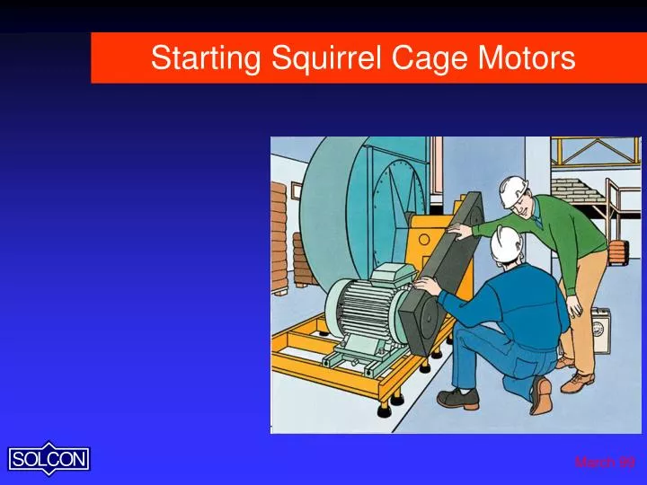
Starting Squirrel Cage Motors Seminar March 99
Electronic soft starters Part Presentation Slides 1 Starting AC Motors 3 - 22 2 Electronic soft starters 23 - 36 3 Digital soft starter “RVS-DN” 37 - 132 4 Analog soft starters “RVS-N“ 133 - 139 5 Analog soft starter “Solstart” 140 - 143
Starting the motor Three basic methods for starting squirrel cage motors : * Full voltage- Direct On Line (D.O.L.) * Reduced voltage- Electro mechanical methods * Reduced voltage- Electronic methods
Un t Direct On Line (D.O.L.) Starting Starting Voltage- Full voltage at starting 100% Un
Istart In RPM Direct On Line Starting Starting Current- Typically 500-800% In, depends on motor design.
Mmax Mstart Mn Moperation Load RPM Direct On Line Starting * Starting Torque (M start)- Typically 150 - 180% Mn * Max Torque (Mmax) - Break Down Torque can reach 220% Mn
Macceleration Mload Direct On Line Starting Acceleration Torque - The difference between motor and load torque's, determines the Acceleration Time.
Nn t Direct On Line Starting Start Time- the high Acceleration Torque results in fast acceleration of motor speed, typically less than 1 sec.
Direct On Line Starting 1 sec. Current Inrush
1 sec. Mechanical Shock Direct On Line Starting
Reducing Starting Current & Torque Reducing Inrush Current is essential : * When starting from weak power supplies like fully loaded transformers, long cables, diesel generators, etc. Reducing mechanical shock is essential : * To increase life expectancy of belts, gears, shafts and motors. * To reduce maintenance requirements * To prevent damage to fragile loads
Reducing Starting Current & Torque * Reducing Inrush Current & Mechanical Shock in squirrel cage motors can be done by reducing motor voltage during starting * Reducing voltage during starting can be done by the old electro- mechanical systems like Star-delta, Auto-transformer, Part winding, Starting Resistors or by modern Electronic Soft Starters
Reducing Starting Voltage When Starting Voltage is reduced: * Starting torqueis reduced in square proportion to voltage reduction * Starting currentis reduced in direct or square proportion to voltage reduction - depending on starting method
Direct On Line - Summary Advantages: Simple, Small size, Low price. Disadvantages: * High inrush current 500-850% In which may cause voltage drops in supply system, nuisance tripping & light dimming. * High starting torque 150-250% Mn which may cause mechanical damages to gears, transmissions and fragile loads. Price factor : 0 .2 - 1 times Soft starter
D Un Y U Y UY= 58% Un t transfer point Y/D Starting Starting voltage - Y connected (58% Un), transfer to Delta (100% Un) by timer - open loop control.
I start DOL Reduced Starting Current D Y I Y RPM Transfer point Y/D Starting Starting Current - Typically 250% In, current is reduced in square proportion to voltage reduction
M DOL Reduced Starting & Acceleration Torque D Y M Y Moperation M acceleration RPM Y/D Starting Starting Torque - Reduced by the square proportion to voltage reduction, the voltage remains constant during most of the starting time. M start Y = (0.58)2 x M start (A.T.H) = 0.33 x M start
D Y/ D.O.L Nn t Y/D Starting Start Time - Extended acceleration time due to lower acceleration torque
1 sec. Y/D Starting - Current Inrush current spike during transfer from Y to D (especially in varying type loads)
Y/D Starting - Summary Advantages: Simple, Small size, Inexpensive (in lower ratings), Lower starting currents. Disadvantages: * Non-adjustable starting characteristics * Possible high switching current & torque (expensive closed transition) * Open loop control * 6 wires to the motor * No optional features (only soft start) * No motor protection. Price factor: .6 - 2 times Soft starter
Auto-transformer Starting Advantages:Lower starting currents. Disadvantages: * Bulky * Expensive * Limited number of operations per hour * Complicated change of starting parameters * Switching transients - expensive closed transition. Price factor : 1 - 2 times Soft starter
L1 • 3 L2 L3 Electronic Soft Starters Using 6 Thyristors (SCRs), 2 per phase, in an anti-parallel connection
Vc Thyristors (SCR’s) firing system The left thyristor conducts during the positive period of the sine wave, when Vc is On and can be turned Off when the current is at zero crossing.
Vc Thyristors (SCR’s) firing system The other thyristor is coupled in an anti-parallel method and conducts in the negative half cycle.
Zero Crossing Phase Control U start t soft start Thyristors (SCR’s) firing system Thyristor firing controls the soft starter output voltage
Un U4 U3 U2 Voltage ramp U1 U start Time t1 t2 t3 t4 t soft start Voltage Ramp-up Voltage ramp-up (without Current Limit)
I start Current with Soft-starter I soft In RPM Current Ramp-up Current Ramp-Up (without Current Limit)
I start Un Current limit Current Limit 4 X U start I n Time RPM t soft start Current ramp-up with Current Limit Voltage & current increases until the current reaches Current Limit. The Voltage will not increase until current begins reducing, as the motor approaches nominal speed.
Calculating motor’s torque Motor torque with soft starter Msoft = ( U soft / U n) 2* Mstart Assuming M start = 1.8 * M n Assuming U start =0.5 Un (0.25 Un) Msoft = (0.25) * 1.8 = 0.45 M start Torque is reduced by the square of the voltage reduction
M V M D.O.L TU6 U5 U4 TU5 U3 TU4 TU3 U2 U1 TU2 TU1 RPM t1 t2 t3 t4 t5 t6 t1 t2 t3 t4 t5 t6 Motor Voltage / Torque Ratio
M max M start Msaddle without current limit with current limit Mn RPM Torque with & without Current Limit Torque / Voltage curves with and without Current Limit
with current limit 1 sec. Soft Starter - Current Inrush
1 sec. Soft Starter - Mechanical shock
Y / D Soft-starter D.O.L Motor current Motor torque Summary Motor torque
Soft starter - summary Disadvantages: Relatively expensive, higher sophistication Advantages: * Solid state - no moving parts, less maintenance * Reduced starting current & mechanical shock * Smooth, stepless acceleration & deceleration * Closed current loop starting * Easy adjustments for all applications * Comprehensive motor protection package * Special features: “Pump Control”, Soft stop, Slow speed with electronic reversing, Dual adjustment, Energy saver, etc.
Soft Starter Line • RVS-DN Digital 8-2700A 220 - 690V • RVS-DN “ 105-390A 1000V • RVS-DN “ 8-2700A Marine Type • HRVS-DN “ 60 - 800A 1500-7200V • RVS-N Analogue 8-170A 220 - 600V • SOLSTART “ 8-17A 220 - 690V • SEM-N (navy) “ 8-31A 220 - 440V
RVS-DN Digital Soft Starters for Heavy Duty Industrial Applications
The RVS-DN family Size B Size D Size A Size C 55 - 90 KW 250 - 450 KW 4 - 37 KW 110 - 220 KW
RVS-DN Advantages • Heavy Duty Design: 400% In, 30 sec. at 50°C, 4 starts an hour • Comprehensive Range: 8-2700A, 220-1000V • Second Generation Digital Field proven experience • Fully featured: Control, Protection & Supervision • Comprehensive Motor Protection • User Friendly: Default settings, LCD display, Selectable languages
UL UL Approved : 8-820A, 1100A and above are designed to meet UL requirements USA cUL Approved : 8-820A 1100A and above are designed to meet cUL requirements cUL Canada CE Approved (EMC & Safety) : 8-1400A 1800A and above are designed to meet CE requirements European Lloyd’s Approved (ENV 1 & ENV 2) : 8-1400A 1800A and above are designed to meet Lloyd’s specifications for ENV1 & 2 requirements Marine & Offshore RVS-DN Approvals
Selector Guide Starter Frame Motor HP Type Size230V460V575V RVS-DN 8 A2.5 5 7.5 RVS-DN 17 5 10 15 RVS-DN 31 10 20 30 RVS-DN 44 15 30 40 RVS-DN 58 20 40 50 RVS-DN 72 25 50 60 RVS-DN 105 B 40 75 100 RVS-DN 145 50 100 125 RVS-DN 170 60 125 150 RVS-DN 210 C 75 150 200 RVS-DN 310 125 200 300 RVS-DN 390 150 300 350 Starter should be selected according to motor’s Full Load Amp and starting conditions
Selector Guide Starter Frame Motor HP Type Size 230V 460V575V RVS-DN 460 D 200 400 450 RVS-DN 580 250 500 550 RVS-DN 820 300 700 900 RVS-DN 1100 E * 450 900 1100 RVS-DN 1400 500 1100 1500 RVS-DN 1800 RVS-DN 2100 F* RVS-DN 2700 Starter must be selected according to motor’s Full Load Amp and starting conditions * To be used with a by-pass contactor
Keypad Isolated Power Inputs (Prog.) Supply Preparation I measurements LEDs For By-pass All Protection Display MICRO Remain Active Firing circuitry SCRs PROCESSOR LCD V measurements Display Options : Memory : Relay M * RS-485 Comm. Outputs Statistics * Insulation (Prog.) Faults * Tachometer in * Analogue Out * Thermistor in RVS-DN Block Diagram
Line To by-pass (option) LCD (selectable languages) LEDs (status display) Control terminals (Plug-in) IP 20 Finger protected for safe operation To Motor Size A (8-72A)
Front protected for safe operation Size B (105-170A) (Bus bar cover removed) Line To Motor Power Section Control Module (Identical for sizes B-F)
Line (Bus bar cover removed) To Motor C/T Power Section Control Module Front protected for safe operation Size C (210-390A)
Line To motor To by-pass C / T Preparation for By-pass
L 1 L 2 L 3 M Preparation for By-pass
Line Load (Bus bar cover removed) C/T Power section Control module Size D (460-820A)
Line Power Section C/T Control Module To Motor Size E (1100-1800A)