Download

1 / 53
560 likes | 803 Views
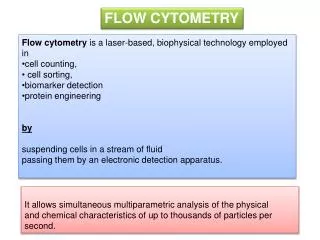
BMS 631 - LECTURE 7 Flow Cytometry: Theory J. Paul Robinson Professor of Immunopharmacology& Biomedical Engineering Purdue University. Detectors & Fluidics. Notes: Material is taken from the course text: Howard M. Shapiro, Practical Flow Cytometry , 3nd edition (1994), Wiley-Liss, New York.

E N D
BMS 631 - LECTURE 7Flow Cytometry: TheoryJ. Paul RobinsonProfessor of Immunopharmacology& Biomedical EngineeringPurdue University Detectors & Fluidics • Notes: • Material is taken from the course text: Howard M. Shapiro, Practical Flow Cytometry, 3nd edition (1994), Wiley-Liss, New York. • RFM =Slides taken from Dr. Robert Murphy • MLM – Material taken from Melamed, et al, Flow Cytometry & Sorting, Wiley-Liss, 2nd Ed. Hansen Hall, B050 Purdue University Office: 494 0757 Fax 494 0517 email: robinson@flowcyt.cyto.purdue.edu WEB http://www.cyto.purdue.edu 3rd Ed. Shapiro 127-133
Detectors • Light must be converted from photons into volts to be measured • We must select the correct detector system according to how many photons we have available • In general, we use photodiodes for forward scatter and absorption and PMTs for fluorescence and side scatter
Silicon photodiodes • A silicon photodiode produces current when photons impinge upon it (example are solar cells) • Does not require an external power source to operate • Peak sensitivity is about 900 nm • At 900 nm the responsivity is about 0.5 amperes/watt, at 500 nm it is 0.28 A/W • Are usually operated in the photovoltaic mode (no external voltage) (alternative is photoconductive mode with a bias voltage) • Have no gain so must have external amps • quantum efficiency ()% = 100 x (electrons out/(photons in)
PMT • Produce current at their anodes when photons impinge upon their light-sensitive cathodes • Require external powersource • Their gain is as high as 107 electrons out per photon in • Noise can be generated from thermionic emission of electrons - this is called “dark current” • If very low levels of signal are available, PMTs are often cooled to reduce heat effects • Spectral response of PMTs is determined by the composition of the photocathode • Bi-alkali PMTs have peak sensitivity at 400 nm • Multialkali PMTs extend to 750 nm • Gallium Arsenide (GaAs) cathodes operate from 300-850 nm (very costly and have lower gain)
Signal Detection - PMTs Secondary emission Cathode Anode Amplified Signal Out Photons in End Window Dynodes • Requires Current on dynodes • Is light sensitive • Sensitive to specific wavelengths • Can be end`(shown) or side window PMTs
Photomultiplier tubes (PMT’s) The PMTs in an Elite. 3 PMTs are shown, the other 2 have been removed to show their positions. A diode detector is used for forward scatter and a PMT for side scatter. The Bio-Rad Bryte cytometer uses PMTs for forward and wide angle light scatter as well as fluorescence
PMTs • High voltage regulation is critical because the relationship between the high voltage and the PMT gain is non-linear (almost logarithmic) • PMTs must be shielded from stray light and magnetic fields • Room light will destroy a PMT if connected to a power supply • There are side-window and end-window PMTs • While photodiodes are efficient, they produce too small a signal to be useful for fluorescence
Diode Vs PMT • Scatter detectors are frequently diode detectors Sample stream Back of Elite forward scatter detector showing the preamp Front view of Elite forward scatter detector showing the beam-dump and video camera signal collector (laser beam and sample sheath are superimposed)
Types of PMTs Side Window Signal out High voltage in
High Voltage on PMTs • The voltage on the PMT is applied to the dynodes • This increases the “sensitivity” of the PMT • A low signal will require higher voltages on the PMT to measure the signal • When the voltage is applied, the PMT is very sensitive and if exposed to light will be destroyed • Background noise on PMTs is termed “dark noise” • PMTs generally have a voltage range from 1-2000 volts • Changing the gain on a PMT should be linear over the gain range • Changing the voltage on the PMT is NOT a linear function of response
Avalanche Photodiodes (APD’s) • Combines the best features of PMTs and photodiodes • High quantum efficiency, good gain • Gain is 102-103 (much less than PMTs) • Problem with high dark current Image From: http://micro.magnet.fsu.edu/primer/java/photomicrography/avalanche/
CCDs • Charge Coupled devices (CCD) usually in our video cameras (also called charged transfer devices) • light causes accumulation of electric charge in individual elements which release the charge at regular intervals • Useful in imaging because they can integrate over time • Not fast enough for flow cytometry application in general
Summary so far…. • Photodiodes can operate in two modes - photovoltaic and photoconductive • PMTs are usually used for fluorescence measurements • Photodiodes are usually used for scatter • PMTS are sensitive to different wavelengths according to the construction of the photocathode • PMTs are subject to dark current • Voltages and gain are not linear • Photodiodes are more sensitive than PMTs but because of their low gain, they are not as useful for low level signals (too much noise)
Flow Systems and Hydrodynamics • Getting the cells in the right place (at the right time)! (Shapiro, pp 133-143 - 3rd ed)
Basics of Flow Cytometry Fluidics • cells in suspension • flow in single-file through • an illuminated volume where they • scatter light and emit fluorescence • that is collected, filtered and • converted to digital values • that are stored on a computer Optics Electronics [RFM]
Fluorescence signals Focused laser beam Flow Cytometry:The use of focused light (lasers) to interrogate cells delivered by a hydrodynamically focused fluidics system. Sheath fluid Flow Cell
Fluidics - Differential Pressure System [RFM] From C. Göttlinger, B. Mechtold, and A. Radbruch
3-way valve Flowcell • Positive Displacement Syringe Systems • 1-2 ms-1 flow rate • Fixed volume (50 l or 100 l) • Absolute number calculations possible • Usually fully enclosed flow cells Syringe + + + + + + + + + 100 l Waste Sample Sample loop Fluidics Systems • Positive Pressure Systems • Based upon differential pressure • between sample and sheath fluid. • Require balanced positive pressure • via either air or nitrogen • Flow rate varies between 6-10 ms-1
Hydrodynamics and Fluid Systems • Cells are always in suspension • The usual fluid for cells is saline • The sheath fluid can be saline or water • The sheath must be saline for sorting • Samples are driven either by syringes or by pressure systems
Fluidics • Need to have cells in suspensionflow in single file through an illuminated volume • In most instruments, accomplished by injecting sample into a sheath fluidas it passes through a small (50-300 µm) orifice [RFM]
Fluidics • When conditions are right, sample fluid flows in a central core that does not mix with the sheath fluid • This is termed Laminar flow [RFM]
Fluidics - Laminar Flow • Whether flow will be laminar can be determined from the Reynolds number • When Re < 2300, flow is always laminar • When Re > 2300, flow can be turbulent [RFM]
Fluidics • The introduction of a large volume into a small volume in such a way that it becomes “focused” along an axis is called Hydrodynamic Focusing [RFM]
Fluidics The figure shows the mapping between the flow lines outside and inside of a narrow tube as fluid undergoes laminar flow (from left to right). The fluid passing through cross section A outside the tube is focused to cross section a inside. [RFM] From V. Kachel, H. Fellner-Feldegg & E. Menke - MLM Chapt. 3
Fluidics Notice how the ink is focused into a tight stream as it is drawn into the tube under laminar flow conditions. Notice also how the position of the inner ink stream is influenced by the position of the ink source. [RFM] V. Kachel, H. Fellner-Feldegg & E. Menke - MLM Chapt. 3
Fluidics • How do we accomplish sample injection and regulate sample flow rate? • Differential pressure • Volumetric injection [RFM]
Fluidics - Differential Pressure System • Use air (or other gas) to pressurize sample and sheath containers • Use pressure regulators to control pressure on each container separately [RFM]
Fluidics - Differential Pressure System • Sheath pressure will set the sheath volume flow rate (assuming sample flow is negligible) • Difference in pressure between sample and sheath will control sample volume flow rate • Control is not absolute - changes in friction cause changes in sample volume flow rate [RFM]
Fluidics - Volumetric Injection System • Use air (or other gas) pressure to set sheath volume flow rate • Use syringe pump (motor connected to piston of syringe) to inject sample • Sample volume flow rate can be changed by changing speed of motor • Control is absolute (under normal conditions) [RFM]
Syringe systems • Bryte HS Cytometer Syringe 3 way valve
Fluidics - Volumetric Injection System H.B. Steen - MLM Chapt. 2
Flow Cell Coverslip Signals Waste Flow Cell Microscope Objective Coverslip Microscope Objective Waste Hydrodynamic Systems Signals
Fluidics - Particle Orientation and Deformation • As cells (or other particles) are hydrodynamically focused, they experience different shear stresses on different points on their surfaces (an in different locations in the stream) • These cause cells to orient with their long axis (if any) along the axis of flow [RFM]
Fluidics - Particle Orientation and Deformation • The shear stresses can also cause cells to deform (e.g., become more cigar-shaped) [RFM]
Fluidics - Particle Orientation and Deformation “a: Native human erythrocytes near the margin of the core stream of a short tube (orifice). The cells are uniformly oriented and elongated by the hydrodynamic forces of the inlet flow. b: In the turbulent flow near the tube wall, the cells are deformed and disoriented in a very individual way. v>3 m/s.” Image fromV. Kachel, et al. – Melamed Chapt. 3 [RFM]
Fluidics - Flow Chambers • The flow chamber • defines the axis and dimensions of sheath and sample flow • defines the point of optimal hydrodynamic focusing • can also serve as the interrogation point (the illumination volume) [RFM]
Closed flow cells Laser direction
Coulter XL Sheath and waste system Sample tube
Fluidics - Flow Chambers • Four basic flow chamber types • Jet-in-air • best for sorting, inferior optical properties • Flow-through cuvette • excellent optical properties, can be used for sorting • Closed cross flow • best optical properties, can’t sort • Open flow across surface • best optical properties, can’t sort [RFM]
Fluidics - Flow Chambers Flow through cuvette (sense in quartz) [RFM] H.B. Steen - MLM Chapt. 2
Fluidics - Flow Chambers Closed cross flow chamber [RFM] H.B. Steen - MLM Chapt. 2
Hydrodynamic Systems Sample in Sheath Piezoelectric crystal oscillator Sheath in Fluorescence Sensors Laser beam Scatter Sensor Sheath Core
Hydrodynamically focused fluidics Signal • Increase Pressure: • Widen Core • Increase turbulence
Hydrodynamic Systems Injector Tip Flow Cell Sheath fluid Fluorescence signals Focused laser beam
Flow chamber blockage A human hair blocks the flow cell channel. Complete disruption of the flow results.
Bryte Fluidic Systems Detectors • Sample Collection and hydrodynamics Bryteb.mpg
Detection Systems Shown above is the Bryte HS optical train - demonstrating how the microscope-like optics using an arc lamp operates as a flow detection system. First are the scatter detectors (left side) followed by the central area where the excitation dichroic can be removed and replaced as necessary. Behind the dichroic block is the arc lamp. To the right will be the fluorescence detectors. Fluorescence Detectors and Optical Train Brytec.mpg
Injector Tip Sheath fluid Fluorescence signals Focused laser beam Flow Cell