Download
1 / 68
680 likes | 870 Views
RT 255 C Cross Sectional Anatomy. Week 1 FINAL 4-13-09. Name the Sectional Planes. A. B. C. D. Oblique and Transverse. Used for imaging of heart. Commonly used in MR and sonography. Axial (Transverse) Planes. 1 2 3 4 5 6. Axial Scout. Axial (cross sectional). Sagittal Plane.

E N D
RT 255 CCross Sectional Anatomy Week 1 FINAL 4-13-09
Name the Sectional Planes A B C D
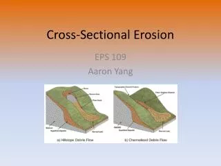
Oblique and Transverse Used for imaging of heart. Commonly used in MR and sonography
Axial (Transverse) Planes • 1 • 2 • 3 • 4 • 5 • 6
Sagittal Plane • 1 • 2 • 3
Coronal Plane • 1 • 2 • 3 • 4 • 5
Both Radiation: Why CT vs. Radiography • Superimposition • Contrast Resolution • Less scatter • One exposure
Similar to Radiography • Radiopaque are white • Bone • Prosthesis • Lower density images are gray • Fat • Muscles • Organs • Very low density are black • Air
Fundamentals of CT • Primary data sent to computer • Calculated according • to algorithm • Data assembled into a matrix • Each sectional slice is displaced • on cathode ray tube Cross sectional Tube rotates around patient Detectors measures primary data
Generations of Scanners • First generation • 1 • 2 • 3 • 4 • Second generation • 1 • 2 • 3 • 4
Third Generation • Rotate/ rotate • More than 750 detectors • 1-10 seconds
Fourth Generation • Rotate only • Fixed detectors • More detectors • Higher dose to PT
Technical Aspects • Remnant radiation is collected • 1 • 2 • Electrical signal digitized • Each signal assigned a number • Signals combined to form digital image • Field of View (FOV) determines amount of data to be displayed on monitor
Breakdown of the Digital Image • Array of numbers • 1 • Pixel • 1 • 2 • Voxel • 1 • 2 • 3
System Components • Computer • Operators console • Gantry • Table
Computer • Four basic functions • 1. • 2 • 3 • 4
Data Acquisition • Tech chooses various parameters • 1 • 2 • 3 • 4
Image Reconstruction • Digitizes raw data • Computer performs mathematical computations on a temporary storage system • Host computer has limited storage capacity • Reconstruction takes a few seconds
Long term Storage • After reconstruction it is transferred to another storage medium • Those temporary images on the host computer are archived separately as an independent study that can be retrieved later
Image display • Can be viewed on a video monitor • Tech and doctor can communicate with host computer to view images • Can manipulate images • 1 • 2 • Image resolution lost with reconstruction in other planes
Gantry • Circular • Aperture is the hole PT goes in • Houses • Detector, slip ring, generator and x-ray tube • Tube similar to x-ray tube • Must withstand higher amounts of heat • Can be tilted 30 degrees forward and back
Table • Automated device linked to gantry & computer • Moves in increments • According to protocol • Made of wood or low density carbon composite • Has a weight limit
Control Console • Where the tech controls the scanner • Has a keyboard, display monitor & mouse • Allows tech to control • 1. • 2 • 3 • 4
Image Manipulation • Windowing • 1. • Window width • 1 • 2 • 3 • Window level • 1 • 2
Windowing Window width 400 Window level 35 Window width 2200 Window level 400
Factors Affecting Image Quality • Spatial resolution • Contrast resolution • Noise • Artifacts • Patient factors • Scan times • Scan diameter
Spatial Resolution • What happens to resolution with smaller phosphor crystals in standard film screen systems? • Is a function of pixel size • Smaller: better detail • Thinner slices: increased detail
Ability to distinguish adjacent tissue In CT it is better than in conventional x-ray Less scatter Appears as graininess Low noise is smooth to the eye High noise is blotchy and spotty As noise increases contrast resolution decreases Contrast Resolution and Noise
Artifacts • Streak artifacts • Metallic objects, pacemakers, and prosthesis • High concentration barium
Patient Factors • Motion • Size of patient