Download
1 / 21

E N D
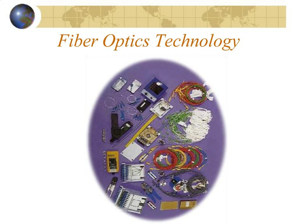
1. Fiber Optics Technology
2. Introduction to Optical Fibers. Fibers of glass
Usually 120 micrometers in diameter
Used to carry signals in the form of light over distances up to 50 km.
No repeaters needed.
3. Introduction (Cont�) Core � thin glass center of the fiber where light travels.
Cladding � outer optical material surrounding the core
Buffer Coating � plastic
coating that protects
the fiber.
4. Evolution of Fiber 1880 � Alexander Graham Bell
1930 � Patents on tubing
1950 � Patent for two-layer glass wave-guide
1960 � Laser first used as light source
1965 � High loss of light discovered
1970s � Refining of manufacturing process
1980s � OF technology becomes backbone of long distance telephone networks in NA.
5. Advantages of Optical Fibre
Thinner
Less Expensive
Higher Carrying Capacity
Less Signal Degradation& Digital Signals
Light Signals
Non-Flammable
Light Weight
6. Areas of Application Telecommunications
Local Area Networks
Cable TV
CCTV
Optical Fiber Sensors
7. Type of Fibers Optical fibers come in two types:
Single-mode fibers � used to transmit one signal per fiber (used in telephone and cable TV). They have small cores(9 microns in diameter) and transmit infra-red light from laser.
Multi-mode fibers � used to transmit many signals per fiber (used in computer networks). They have larger cores(62.5 microns in diameter) and transmit infra-red light from LED.
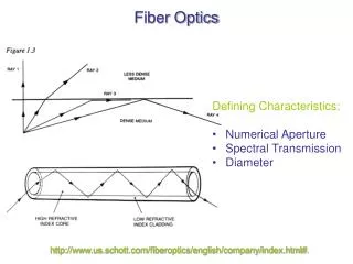
8. How Does Optical Fibre Transmit Light?? Total Internal Reflection.
Fibre Optics Relay Systems has
-Transmitter
-Optical Fibre
-Optical Regenerator
-Optical Receiver
9. Total Internal Reflection in Fiber
10. How are Optical Fibre�s made?? Three Steps are Involved
-Making a Preform Glass Cylinder
-Drawing the Fibre�s from the preform
-Testing the Fibre
11. Testing of Optical Fiber Tensile Strength
Refractive Index Profile
Fiber Geometry
Information Carrying Capacity
Operating temperature/humidity range
Ability to conduct light under water
Attenuation
12. Optical Fiber Laying Mechanical Linking
Includes coupling of two connectors end to end
Optical distribution frames allow cross connect fibers from by means of connection leads and optical connectors
Soldering:
This operation is done with automatic soldering machine that ensures:
Alignment of fiber�s core along the 3 axis
Visual display in real-time of the fibers soldering
Traction test after soldering (50 g to 500 g)
13. Optical Fiber Laying (Cont�) Blowing
Used in laying optical cables in roadways.
Cables can be blown in a tube high density Poly Ethylene
Optical fiber is then blown in the tube using an air compressor which can propel it up to 2 kilometers away.
14. Tools of Trade Cleaning fluid and rags
Buffer tube cutter
Reagent-grade isopropyl alcohol
Canned air
Tape (masking or scotch)
Coating strip
Microscope or cleaver checker
Splicer
Connector supplies
15. Fiber Optics Test Kit Features
Includes Smart FO Power Meter and Mini LED or laser source
FO test lite software for data logging
Tests all networks and cable plants
New versions of Gigabit Ethernet
Low Cost
Applications
Measure optical power or loss
Trouble shooting networks
16. Protecting Fibers Tougher than copper wires
Designed in three concentric layers
Core � Cladding � Buffer
Two basic buffer types
Tight buffer
Loose tubes
17. Implementation of Different LANs IEEE 802.3
FOIRL
Fiber optic inter repeater link
Defines remote repeaters using fiber optics
Maximum length � 1000 meters between any two repeaters.
18. IEEE 802.3 (Cont�) 10BASEF
Star topology with hub in the center
Passive hub:
Short cables
No cascading
Reliable
Active hum:
Synchronous
May be cascaded
Do not count as one repeater
Any 10BASEF active hub must have at least two FOIRL ports
19. Token Ring Advantages
Long range
Immunity to EMI/RFI
Reliability
Security
Suitability to outdoor applications
Small size
Compatible with future bandwidth requirements and future LAN standards
20. Token Ring (Cont�) Disadvantages
Relatively expensive cable cost and installation cost
Requires specialist knowledge and test equipment
No IEEE 802.5 standard published yet
Relatively small installed base.
21. Fiber Distributed Data Interface Stations are connected in a dual ring
Transmission rate is 100 mbps
Total ring length up to 100s of kms.
22. Conclusion