Download
1 / 25
260 likes | 563 Views
CMS Phase I upgrades. LHCC September 2009 Meeting. Upgrade Scope. Agreed at the May 2008 Upgrades Workshop http://indico.cern.ch/conferenceDisplay.py?confId=28746. Phase I Upgrades issues. Meeting at FNAL next month to discuss status of phase I and Phase 2 Upgrades For Phase I

E N D
CMS Phase I upgrades LHCC September 2009 Meeting J. Nash - CMS Upgrades
Upgrade Scope Agreed at the May 2008 Upgrades Workshop http://indico.cern.ch/conferenceDisplay.py?confId=28746 J. Nash - CMS Upgrades
Phase I Upgrades issues • Meeting at FNAL next month to discuss status of phase I and Phase 2 Upgrades • For Phase I • Quantify physics improvements as a function of luminosity • Verify robustness for both peak and integrated luminosity • For Phase 2 • Major efforts in two areas which span multiple sub-systems • Incorporating the tracking in the Level 1 Trigger • Forward Calorimetry at high luminosity • Two cross-detector working groups set up • Regular meetings ongoing • Examine progress and plan work at the FNAL meeting • For today: • Brief look at status of Phase I work, emphasis on areas near the beampipe J. Nash - CMS Upgrades
DOH & AOH mother board + AOH’s Power board endflange prints Layer 3 & 1+2 20 BPIX supply tube FPIX service cylinder 10 0 80 100 20 40 60 Current Pixel System with Supply Tubes / Cylinders Thickness of Supply Tube inserstion envelope for FPIX 10mm 15mm J. Nash - CMS Upgrades
BPIX & Supply Tube with AOH, DOH, PCBs & Fibres J. Nash - CMS Upgrades
Move DOH & AOH boards back by 50-60cm DOH & AOH mother board + AOH’s power board 20 FPIX service cylinder 10 0 80 100 20 40 60 Shift Material out of tracking Volume 10mm 15mm - change in FPIX insertion envelope - increase FPIX radius +5mm - possible due to tilted endposition of BPIX supply tube talk S.Streuli new BPIX modules with long pigtails (~0.95m) ( micro-twisted pairs) J. Nash - CMS Upgrades
Z loc. TBD suggest 491mm from IP 396 291 η = 1.3 η = 1.6 64.8 161 45 30 60 2x8s 2x8s 2x8s 2x8s 2x8s 2x8s BPIX / FPIX Envelope Definition for 4 Hit Pixel System Increase by +5mm η = 2.1 η = 2.5 All Identical disks (1st and 2nd disks in locations to maximize 4-hit eta coverage) 6 disks = (6x68) outer + (6x44) inner = 672 2x8 modules (10752 ROCs) J. Nash - CMS Upgrades
BPIX Upgrade Phase 1 (2013) 1216 modules (1.6 x present BPIX) J. Nash - CMS Upgrades
Each half shell has 10 cooling loops Each supply tube feeds 5 cooling loops Angle bend (~30) during insertion taken by carbon fibre hinge Inertion of BPIX – Supplytube System with new CO2 Cooling New axis of rotation (~3 degrees) during pixel insertion Carbon fiber hinge Stainless steel tubes diameter = 1.8mm wall thickness = 100μm J. Nash - CMS Upgrades
Prototype Fabrication Layer 1 100 bar pressure tested Tubes, 50m wall thickness Weight Layer1 42g + 7g CO2 J. Nash - CMS Upgrades
The Half Disk (to be completed) Carbon fiber supporting spokes J. Nash - CMS Upgrades
Checking for clearance as the FPix half-cylinder slides along insertion rails J. Nash - CMS Upgrades
Mock-up of CMS interaction region for insertion tolerance tests Beam Pipe suport BPIX rails FPIX rails J. Nash - CMS Upgrades
Test of long CO2 cooling loop ( as in Layer 1) • Cooling loop of layer 1 for CO2 tests at CERN • CO2 Teststand ( H.Postema & A. Onnella, CERN) • Tests for individual Temp. distribution at Lyon Stainless steel facets used as heater resistors to simulate the power consumption of the sensor modules. J. Nash - CMS Upgrades
Phase I HCAL Upgrades SiPMs in HO • 2RBXs (144 channels) are instrumented with SiPMs to confirm suitability for HO • Packaged to replace HPD in existing RM • Two suppliers: • Hamamatsu (400 pix/mm2) • Zecotek (15K pix/mm2) • Compared in 2009 Test Beam • S/B much higher than HPD • Insensitive to B-field • But gain is temperature-dependent • Consider replacement for HPDs in R1/2 in during 2011 shutdown Peltier Coolers SiPM and interface cards replace HPD 18 SiPMs replace HPD pixels Pedestal Muon signal (not corrected for track path in HO scint.) CMS Physics Week 2009
SiPM in B-field LED data: SiPM/pinDiode Hamamatsu Zecotek Variation is consistent with temperature change: Hamamatsu gain changes 8-10% per deg Zecotek 4-5% per deg Two changes needed: Will want better temp precision (currently 1bit=0.2deg) Also, cross-talk to a specific few channels from control lines - likely an easy board modification Preliminary CMS Physics Week 2009 Vladimir Epshteyn
More Depth Segmentation in HCAL Upgrade 64-Channel HB RMs 48-Channel HE RMs Current 18-Channel RMs 18 June Upgrade Days
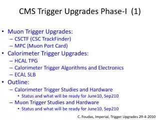
Calorimeter signatures Electrons/Photons Spatially confined in a cluster of 2x2 trigger towers Significantly higher ECAL contribution Isolated e/γ should have low energy deposits in the surrounding area Phase I Trigger Upgrades HCAL Δη x Δφ=0.087x0.087 η ECAL φ e/γ HCAL η • Taus • Confined in 2x3 Clusters • 3 prongs/1 prong + π0s have wider φ profile • Small energy leak in surrounding towers ECAL φ τ HCAL η • Jets • Most of the energy confined in a central core • For jets over 20 Gev the energy is included in a 8x8 region ECAL φ jet
Phase I Calorimeter Trigger Simulation Results: Factor of 2 Michalis Bachtis & Kevin Flood Isolated electrons LHC LHC Taus QCD Rate (kHz) QCD Rate (kHz) SLHC SLHC Factor of 2 rate reduction SLHC SLHC Isolated electrons Taus Efficiency Efficiency LHC LHC Higher Efficiency
Hardware prototype for new trigger architecture J. Nash - CMS Upgrades
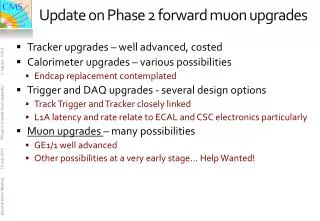
Phase 1 : Muons ME4/2 upgrade motivation Compare 3/4 vs. 2/3 stations: (Triggering on n out of n stations is inefficient and uncertain) Recent simulation with & without the ME4/2 upgrade: The high-luminosity Level 1 trigger threshold is reduced from 48 18 GeV/c Phase I Muon Upgrades Target Rate 5 kHz Rick Wilkinson, Ingo Bloch J. Nash - CMS Upgrades
Five ME+4/2 chambers installed ME4/2 ME4/2 Residual 1 Sep 2009 J. Nash - CMS Upgrades
CSC Factory Production Site at CERN Packing Gas Electronics Strip gluing Loadiing area Chamber FAST site & HV tests Automatic & hand soldering Panel cleaning/gluing area Door Door 20m Panel cleaning Clean room 2 Panel storage and kit preparation Clean room 1 Incoming parts Wire gluing Assembly & Sealing Winding Panel HV test Panel storage Panel storage Strip Gluing 15m 10m 30m 55m Floor plan layout at Bldg 904 (Draft) Based on experience of ME4/2 prototype production the proposed area at 904 of ~ 1000 m2 should be enough to place a factory production and FAST test site. For the completed chambers we need additional storage area of ~ 250m2. J. Nash - CMS Upgrades
Conclusions • Phase I work progressing well • Understanding of the issues surrounding the beampipe is well advanced • Major meeting in October to look at how we go forward J. Nash - CMS Upgrades