Download
1 / 60
620 likes | 1.09k Views
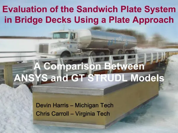
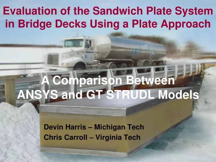
Evaluation of the Sandwich Plate System in Bridge Decks Using a Plate Approach. A Comparison Between ANSYS and GT STRUDL Models. Devin Harris – Michigan Tech Chris Carroll – Virginia Tech. Project Overview. Design Approach. Element Validation. ANSYS Models. Comparison. GT STRUDL Models.

E N D
Evaluation of the Sandwich Plate System in Bridge Decks Using a Plate Approach A Comparison BetweenANSYS and GT STRUDL Models Devin Harris – Michigan Tech Chris Carroll – Virginia Tech
Project Overview Design Approach Element Validation ANSYS Models Comparison GT STRUDL Models SPS Introduction
Introduction to SPS Pre-fab Panels • Advantages • Lightweight • Rapid installation • New/rehab • Disadvantages • Cost • Limited application • No design provisions • Developed by Intelligent Engineering • Maritime industry • Bridge Application (deck)
Prefabricated Decks/Bridges Structured Panel Deck Fabricated panel – limited girder configuration Wide girder spacing Larger cantilevers Fast erection
Half-Scale Bridge (VT Laboratory) • Span ≈ 40 ft; width ≈ 14.75 ft • Deck ≈ 1 in. (3.2-19.1-3.2) • 8 SPS panels • Transversely welded/bolted • Bolted to girders (composite) • 2 girder construction
Shenley Bridge (St. Martin, QC) • Completed - November 2003 • 7 days of total construction • Span ≈ 74 ft; width ≈ 23 ft • Deck ≈ 2 in. (6.4-38-6.4) • 10 SPS panels • Transversely welded/bolted • Bolted to girders (composite) • 3 girder construction
Sequence of SPS Construction ERECT GIRDERS & BRACING LAY PANELS BOLT PANELS TO BEAMS & TOGETHER WELD DECK SEAM
Sequence of SPS Construction ERECT BARRIERS COAT DECK LAY ASPHALT
Prefabricated Decks/Bridges Simple Plate Deck Simple plate – many girder configuration Small girder spacing Short cantilevers Girders attached to deck in factory Very fast erection
Cedar Creek Bridge (Wise County, TX) • 2-Lane rural road • SPS Deck (integral girders) • Span = 3@50 ft • Width = 30 ft • Deck ≈ 1-5/8 in. • 5/16”-1”-5/16”
Current Bridge Projects New Bridge IBRC – Cedar Creek – Texas – June ‘08
Research Objective To develop a simple design procedure for SPS decks for bridge applications
SPS Deck Design Approach AASHTO Deck Design • Design Methods • Linear Elastic (Equivalent Strip) • Inelastic (Yield-Line) • Empirical (R/C only) • Orthotropic Plate • Limit States • Serviceability • Strength • Fatigue SPS Approach (Layered Plate) • Variable loads and B.C.s • Assume deflection controls
Analysis Options Approach primarily dependent on B.C.s • Classical Plate Approach • Navier • Levy • Energy (Ritz) • Finite Element Approach • Shell • Solid • Grid (line elements)
FE Model Approach • Shell Model • Advantages • Ideal for thin elements • Computationally efficient • Membrane/bending effects • Single thru thickness element • Solid Model • Advantages • Realistic geometry representation • Element connectivity • Disadvantages • Element compatibility • Element connectivity • Stacking limitations* • Disadvantages • Can be overly stiff • User error (more likely) • Complicated mesh refinement
Material Properties *Dt = flexural rigidity for layered plate (equivalent to EI for a beam) *Ventsel, E., and Krauthammer, T. (2001). Thin plates and shells:theory, analysis, and applications, Marcel Dekker, New York, NY.
Element Validation (Generic) Midpanel Deflection (wmax) Givens: • Boundary Conditions: Fully Restrained • Material Properties: E=29,000 ksi; n=0.25 • Dimensions: thickness=6” (constant); a=b=L [L/t … 1-200] • Load: q = 0.01 ksi (uniform) ANSYS • Shell 63 (4-node) • Shell 91/93 (8-node) • Solid 45 (8-node) • Solid 95, Solid 191 (20-node) GT STRUDL • BPR (4-node plate) • SBHQ6 (4-node shell) • IPLS (8-node solid) • IPQS (20-node solid)
GT STRUDL Models Element Types SBHQ6 BPR IPLS IPQS
GT STRUDL Models Mesh Verification
GT STRUDL Models Two Dimensional Example IPLQ(2D equivalent of IPLS)Linear Shape Function 60 in. A shape function is the relationship of displacements within an element. IPQQ(2D equivalent of IPQS)Quadratic Shape Function 60 in.
GT STRUDL Models Two Dimensional Example 60 in. One Layer 60 in.
GT STRUDL Models Two Dimensional Example 60 in. Two Layers 60 in.
GT STRUDL Models Two Dimensional Example 60 in. Three Layers 60 in.
GT STRUDL Models Two Dimensional Example 60 in. Four Layers 60 in.
GT STRUDL Models Two Dimensional Example 120 in. 120 in.
GT STRUDL Models Two Dimensional Example
GT STRUDL Models Aspect Ratios (IPLS vs. IPQS) Small Aspect Ratios Large Aspect Ratios
SPS Models • Case I • Simple Support on all edges • Cold-formed angles – assume minimal rotational restraint
SPS Models • Case II • Simple supports perpendicular to girders • Fixed supports along girders • Rotation restrained by girders & cold-formed angles
SPS Models • Case III • Full restraint on all edges • Rotation restrained by girders & cold-formed angles
GT STRUDL Models Boundary Conditions/Symmetry Reduced Model: 86,400 Elements102,487 Joints307,461 DOF Full Model: 345,600 Elements406,567 Joints1,229,844 DOF
Simple – Simple Simple – Fixed Fixed – Fixed 2” Thick Plate 1” Thick Plate Symmetry GT STRUDL Models Model Construction
GT STRUDL Models Model Construction
GT STRUDL Models ½” ½” Model Construction
Stiffness Analysis GTSES GTHCS GT STRUDL Models The GTHCS solver partitions the global stiffness matrix into hyper-column blocks of size VBS, and stores these blocks on the computer hard drive, with only two of these blocks residing in the virtual memory at a time reducing the required amount of virtual memory space. Model Construction DPM-w-selfbrn, The module 'SPWNDX' may not be branched to recursively
Summary of Element Validity All Elements are capable of Modeling thin plates, but consideration must be given to mesh density. Especially, thru thickness density for solid elements • ANSYS Solids • Converged with single thru thickness element • ANSYS Shells • Minimal mesh refinement required for convergence • STRUDL Plate/Shells • Converged but no multiple layer capabilities • STRUDL Solids • Converged with sufficient thru thickness refinement
Layered element for composite materials Redraw Issues in GT Menu Contour plots without mesh Undo Button in GT Menu Suggested Improvements
Model Validation – SPS Panel Full Scale SPS Panel
Model Validation – SPS Panel SPS Plate (0.25” plates; 1.5” core) Support by W27 x 84 beams Loaded to 77.8 k with concrete filled tires (assumed 10” x 20”)
Experimental vs. Shell Model PredictionsANSYS CASE II (Fixed @ Beams) CASE I (SS) CASE III (Fixed)
Model Validation – SPS Bridge Half-Scale SPS Bridge