Download

1 / 23
230 likes | 320 Views
Boosting: Min-Cut Placement with Improved Signal Delay. Andrew B. Kahng. Igor L. Markov. Sherief Reda. CSE & ECE Departments University of CA, San Diego La Jolla, CA 92093 abk@cs.ucsd.edu. EECS Department University of Michigan Ann Arbor, MI 48109 imarkov@eecs.umich.edu. CSE Department

E N D
Boosting: Min-Cut Placement with Improved Signal Delay Andrew B. Kahng Igor L. Markov Sherief Reda CSE & ECE Departments University of CA, San Diego La Jolla, CA 92093 abk@cs.ucsd.edu EECS Department University of Michigan Ann Arbor, MI 48109 imarkov@eecs.umich.edu CSE Department University of CA, San Diego La Jolla, CA 92093 sreda@cs.ucsd.edu VLSI CAD Laboratory at UCSD
Outline • Introduction and motivation • Controlling wirelength distribution • Boosting min-cut placement • Effect of boosting on cut values • Experimental results • Conclusions
Introduction: Min-Cut Placement • Min-cut objective: minimize cut partitions → minimizes total wirelength with the help of terminal propagation • Min-cut partitioning produces slicing outlines
Introduction: Min-Cut Placement • Min-cut objective: minimize cut partitions → minimizes total wirelength with the help of terminal propagation • Min-cut partitioning produces slicing outlines
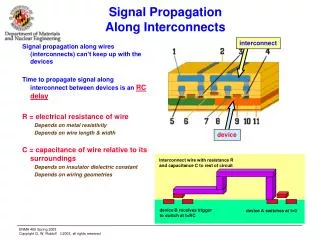
Motivation: Avoiding Global Interconnects • Min-cut placers • Sequentially minimize wirelength, i.e., the routing demand • Do not treat global interconnects in any special way • Global interconnects can severely increase propagation delay since delay is proportional to square of the wirelength take part of critical paths and degrade performance require buffering for electrical sanity have a propagation delay that is equivalent to several clock cycles Conclusion: try to prevent global interconnects
Motivation: Example Case A Case B • Cases A and B: same wirelength & number of cuts • CaseB: no global interconnects (cf. CaseA)
Outline • Introduction and motivation • Controlling wirelength distribution • Boosting min-cut placement • Effect of boosting on cut values • Experimental results • Conclusions
Bounds on Net Length • A net’s HPWL (Half Perimeter Wirelength) is bounded • from below by distances between closest points of incident partitions • from above by distances between furthest points of incident partitions • These bounds are gradually refined during top-down placement • at the beginning lower bounds are ~0s, upper bounds are determined by placement region • at the end, the bounds are close to (or match) HPWL Net L Upper bound = ¾ chip width Lower bound = ¼ chip width
Net L Upper bound reduces; lower bound stays the same Net L Upper bound stays the same; lower bound increases Dichotomy of Lower and Upper bounds Net L
Net Extension Control • Partitioning a block extends a net L if the next two equivalent conditions occur: (1) Cutting L increases the lower bound on its length Or equivalently (2) Not cutting L decreases the upper bound on its length • We use the previous conditions to detect net extension and attempt to curb it via boosting
Boost net L with a boosting factor of 2 L Boosting Min-Cut Placement • Boosting = multiplying a hyperedge (net) weight by a factor • boosting factor • Boosting is used only when a cut can increase a lower bound L
BOOST? BOOST? BOOST? BOOST? To Boost or Not to Boost? YES NO YES NO
Effect of Boosting on Cut Value Case 1 v u • v is connected to a net eligible for boosting, u is not • either can be moved to the right • Boosting factor is 2: the gain of v grows from 1 to 2 • Tie is broken by moving v → no degradation in wirelength, and a global wire is avoided
Effect of Boosting on Cut Value Case 2 v u • v is connected to several nets eligible for boosting, u is not • Boosting factor is 2 on each net: v’s gain grows from 3 to 6 • v has a higher priority → no degradation in wirelength and a global interconnect is eliminated
Effect of Boosting on Cut Value Case 3 v u • v is connected to 2 nets eligible for boosting • Boosting factor is 2 • gain for v increases (from 2 to 4); gain for u is the same (3) • v is moved → wirelength is degraded but global wires are prevented
Summary • Boosting helps in eliminating global interconnects • Boosting may degrade wirelength in some cases • To reduce wirelength degradation, we only boost during first 8 levels • That is where long wires are determined anyway • At the 8th placement level: → The average block perimeter is 1/256 of the original chip perimeter → Global interconnects are already established → No point in further boosting
Outline • Introduction and motivation • Controlling wirelength distribution • Boosting min-cut placement • Effect of boosting on cut values • Experimental results • Conclusions
Experimental Setup • Three industrial benchmarks • Two experiments: • Effect of boosting on the wirelength distribution • Effect of boosting on timing
Experimental Results: Wirelength Histogram (Design A) Percentage change in number of nets (%) Bins (in terms of half the chip’s perimeter) Boosting substantially reduces global interconnects
Experimental Results: Wirelength Histogram (Design B) Percentage change in number of nets (%) Bins (in terms of half the chip’s perimeter) Boosting substantially reduces global interconnects
Conclusions and Future work • By tracking lower/upper bounds, we identify potential long wires • By additionally increasing net weights, we decrease # of long wires • This alters wirelength distribution and reduces global interconnects • Routability is slightly affected, but generally preserved • Boosting tends to improve circuit delay (timing) measured by the worst slack and total negative slack (TNS) • Ongoing work examines the impact of boosting on the number of inserted buffers