Download
1 / 42
450 likes | 696 Views
Adapted from B. Alberts. Molecular Biology of the Cell . 4th Ed. Garland Science: New York, 2002, pp. 638. CdS. Peptide. Quantum Dots for Neuronal Stimulation. Jessica Winter Dr. Christine Schmidt Dr. Brian Korgel. The University of Texas - Austin. 10 nm. 10 nm. Cellular Communication.

E N D
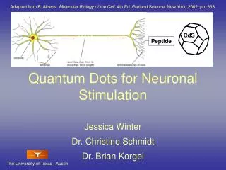
Adapted from B. Alberts. Molecular Biology of the Cell. 4th Ed. Garland Science: New York, 2002, pp. 638. CdS Peptide Quantum Dots for Neuronal Stimulation Jessica Winter Dr. Christine Schmidt Dr. Brian Korgel The University of Texas - Austin
10 nm 10 nm Cellular Communication The Cell Membrane and Cell Receptors. The majority of cellular communication takes place through the binding of signaling molecules to receptor proteins on the membrane surface.www.mhhe.com/biosciesp/2001_gbla/folder_structure/ce/m3/s1
nm Cell Diameter Cell Nucleus Ion Channel Retinal/Cochlear Implant Electrode 20 μm E-Beam Lithography Nanowire Quantum Dot Cell Receptors and Electronics Ion Channel. Adapted from www.mhhe.com/biosciesp/2001_gbla/folder_structure/ce/m3/s1 Nanocrystals (Yellow) Bound to Nerve Cell Receptors. JO Winter, TY Liu, BA Korgel, CE Schmidt. Adv Mats 13, 1673, 2001. Nerve Cell on FET Microelectrode Array. P Fromherz. Chem Phys Chem. 2002, 3, 276
Therapeutics Ion Channels and Signal Tranduction. B. Alberts. Molecular Biology of the Cell. 4th Ed. Garland Science: New York, 2002, pp. 650. Biosensors Retinal Implant. Intraoccular Retinal Prosthesis Group http://www.irp.jhu.edu/projet/ Ion Channel Captured Nanoparticles. T. Aida. et. al. Nature, 423, 628, 2003 Cell Receptor Devices Prosthetics
5 nm Peptide HOOCH2CS SCH2COOH Core HOOCH2CS Peptide Shell Peptide SCH2COOH SCH2COOH Quantum Dots TEM of Nanoparticle. Lattice planes demonstrate crystallinity. CdS Passivated With Ligands. Ligand Passivationelectrically insulates the crystal and provides water solubility. Core-Shell Nanocrystal. The addition of a shell layer can further passivate the particle.
Quantum Dot Properties • Size Tunable Fluorescence • Photostability • Narrow Bandwidth Quantum Dot Photobleaching (L) and Bandwidth (R) WCW Chan, S Nie. Science 281, 2016, 1998. Quantum Dot Fluorescent Emission Wavelengths M Bruchez, Jr., AP Alivisatos, et. al. Science 281, 2013, 1998.
Fluorescent Labeling In Vivo Biolableing ME Akerman et. al. PNAS. 99, 12617, 2002. Bioconjugated Quantum Dots. WCW Chan, S Nie. Science 281, 2016, 1998. Multi-Labeling using Quantum Dots. Bruchez, Jr., AP Alivisatos, et. al. Science 281, 2013, 1998. Conjugation to Neurotransmitters. SJ Rosenthal et. al. JACS 124, 4586, 2002.
HEAT Qdot-Cell Communication Dipole Moment Y Wang, N Herron. J Phys Chem 95:525, 1991. Light 380 nm Electron Tranfer Y Nosaka, et.al. Langmiur 11(4): 1170, 1995. e- + - Heat Transfer SR Sershen, et. al. JBMR 51: 293, 2000. Cell Quantum Dot
Our Goal Exploit qdot – cell binding to create functional interfaces that directly interact with nerve cell receptors
Ion Channels Voltage Gated Ion Channel Activation. A depolarization of the membrane surfaces attracts charged segments of the ion channel protein, opening the pore. H Lodish, A Berk, SL Zipursky, P Matsudaira, D Baltimore, JE Darnell. Molecular Cell Biology. W. H. Freeman & Co., New York: 2000, Figure 21-13.
r Dipole Moment CdSe dipole moment ~ 32 Debye Alivisatos, et. al. J Phys Chem 97:730, 1992. http://hyperphysics.phy-astr.gsu.edu/hbase/electric/dipole.html Nanoparticle Dipole Interaction with Ion Channels. The dipole moment produced by particle optical excitation may be strong enough to elicit a membrane voltage potential change.
- - - - + - - - + + + + + - - - - + + + + + Debye Screening Debye Screening of the Dipole-Induced Electric Field. The electric field is screened by ions in solution, reducing the effective dipole moment.
System Requirements • Efficient Electrical Interactions • Binding Specificity • Measurement of Cell Electrical Response Particle Size Ion Channel ~ 10 nm
_ + _ _ + + Dipole Moment and Crystal Size Crystal with Surface Defects Perfect Crystal Larger Crystal with Surface Defects and Reduced Passivation p = qeR
Aqueous Biologically Compatible Easily Passivated Undesirable Surface Defects Organic Few Surface Defects High Quantum Yield Requires Ligand Exchange for Biocompatibility Step 1: Chemicals Ligand Step 2: Chemicals Vacuum Injection Port N2 Quantum Dot Synthesis
CdCl2 Ligand Na2S NaOH pH ~ 2 Precipitate forms pH ~ 8-9 Qdots Form pH 7 Precipitate Dissolves Qdot Synthesis
_ _ + _ + + _ _ _ _ _ + _ _ + + + _ _ _ _ _ _ _ + + _ _ + _ _ + + Reactant Concentrations Absorbance and Photoluminescence Spectra of CdS Particles at Increasing Reactant Concentration Concentration Charge Screening of the Solvent May Reduce Particle Solubility at Increased Concentration. JO Winter, N Gomez, S Gatzert, BA Korgel, CE Schmidt. Submitted to Langmuir, 2003
Ligand:Cd Ratio pH Cd:S Ratio Size Ligand Length Size Nanocrystal Size Dependence JO Winter, N Gomez, S Gatzert, BA Korgel, CE Schmidt. Submitted to Langmuir, 2003
Cd:S Ratio pH Ligand:Cd Ratio Ligand Length- Different pH Ligand Length PL Quantum Yield PL Quantum Yield. Quantum Yield is maximum for intermediate sized particles ~ 2 nm. JO Winter, N Gomez, S Gatzert, BA Korgel, CE Schmidt. Submitted to Langmuir, 2003
Rapid Crystal Growth Reduced Passivation PL Quantum Yield Larger Smaller Particle Size Growth Mechanism Nanoparticle Quantum Yield As a Function of Particle Size. JO Winter, N Gomez, S Gatzert, BA Korgel, CE Schmidt. Submitted to Langmuir, 2003
(HS(CH2)2NH2, Base) A Quantum Yield Maximum is Still Evidenced. Ligand R Group Altering the Charge of the Ligand R Group Alters the Effect of pH on Particle Size. JO Winter, N Gomez, S Gatzert, BA Korgel, CE Schmidt. Submitted to Langmuir, 2003
Particle Size and Dipole Strength • Quantum Yield Max. at Intermediate Sizes • Smaller Particles Have Lower Dipole • Larger Particles Have Reduced Surface Passivation • Concentration Stability • Ligand R Group (Charge) Alters Qdot Size
Separation Distance System Requirements • Efficient Electrical Interactions • Binding Specificity • Measurement of Cell Electrical Response Ion Channel ~ 10 nm
pH 11 pH 5 pH 7 20 μm Non-Specific Binding Non-Specific Binding of CdS nanocrystals synthesize at different pH values. Cells autofluoresce blue, nanocrystal fluorescence is yellow. Minimum non-specific binding occurs with the same particles that display maximum quantum yield!
QUANTUM DOT 30 nm SECONDARY ANTIBODY ANTI-INTEGRIN ANTIBODY LIPID BILAYER Antibody Attachment to Cells. (To scale) Antibody Conjugation JO Winter, TY Liu, BA Korgel, CE Schmidt. Adv Mat 13(22): 1673, 2001
B A 60 m C Quantum Dot Neuron Interfaces formed with Antibodies. 30 m 30 Antibody-Directed Binding Absorbance data from antibody-qdot complexes. Complexes (dashed) demonstrate both antibody (squares) and qdot peaks (solid). JO Winter, TY Liu, BA Korgel, CE Schmidt. Adv Mat 13(22): 1673, 2001
Cysteine - C QUANTUM DOT 3 nm C G G G G D R S RGDS PEPTIDE INTEGRIN RECEPTOR LIPID BILAYER Peptide Attachment to Cells. Peptide Conjugation GGG- Glycine-Glycine-Glycine Hydrogen R Group, Reduces Steric Hindrance RGDS- Arginine-Glycine-Aspartic Acid- Serine Binds Cell Surface Receptors: Integrins JO Winter, TY Liu, BA Korgel, CE Schmidt. Adv Mat 13(22): 1673, 2001
Spectra of Peptide Qdots Absorbance and PL Emission Spectra of MAA (Black) and Peptide (Red) Passivated Nanocrystals. FTIR Spectra of Free Peptide (Black) and Peptide Conjugated Nanocrystals (Red). Absorbance and PL Emission of MAA (Black) and MAA-Peptide (Red) Conjugated Nanocrystals.
Cleaning Process Anti-Solvent 1-Propanol Nanocrystals Centrifuge Decant Dry Redissolve Absorbance Spectra of Cleaned (Red) and Control (Black) Particles.
9 μm Peptide-Directed Binding Peptide Directed Nanocrystal Labeling After Cleaning. Peptide Directed Nanocrystal Labeling Before Cleaning. 20 μm JO Winter, TY Liu, BA Korgel, CE Schmidt. Adv Mat 13(22): 1673, 2001
Specific Binding • Minimum Non-Specific Binding At Maximum Quantum Yield • Particles May be Conjugated to Antibodies and Peptide • Cleaned Particles May Experience Endocytosis
Separation Distance Microelectrode Array. P Fromherz. Chem Phys Chem. 2002, 3, 276 System Requirements • Efficient Electrical Interactions • Binding Specificity • Measurement of Cell Electrical Response Particle Size Ion Channel ~ 10 nm Patch Clamp. http://www.bio.psu.edu/People/Faculty/Assmann/Lab/techniques.html
Two point probe Electrode Bond pad Cell Bond pads Light 380 nm Cloning ring Example measurement Bove, et al., Bioelectrochem Bioener, 38 (1995) 255. Quantum dots Microelectrode Arrays
90 nm minimum feature size Physical mask Separate insulating layer required 10 nm minimum feature size Mask generated by computer Resist can serve as insulation Comparing Technologies Electron Beam Lithography Photolithography
10 mm x 10 mm Silicon Chip 2 X 1 mm 30 um 35 um 2 X 2 mm 5 x 5 um Electrode Bond Pad Bond Pad Insulated by PMMA Gold Bond Pad Microelectrode Array Design
Microelectrode Array SEM of De-Insulated Electrode (White). PMMA (gray) supports cell growth on Silicon (white) as seen in SEM.
Oscilloscope Microscope Laser Micropositioner Preamplifier Computer Microelectrodes Cell Whole-cell Clamping System. Whole-cell Clamping
K+ Channels Open Computer Induced Voltage Steps Unlabeled (control) Voltage-Step of Cell Whole-Cell Clamping Challenges • Quantum dots can interfere with electrode-cell seal • Cultured cell lines die soon after patch is established • Optimum dipole moment formation may require laser source
Conclusions • Nanocrystal synthesis conditions alter spectroscopic properties • Maximum quantum yield and minimum non-specific binding occurs for intermediate particle sizes • Antibodies and peptides may be conjugated to nanocrystals for targeted cell binding
Future Work • Continue electrical testing of microelectrode arrays • Construct laser source delivery for excitation • Optimize other particle systems (e.g., CdTe, CdSe) • Bind Nanocrystals Directly to Ion Channels
Therapeutics Ion Channels and Signal Tranduction. B. Alberts. Molecular Biology of the Cell. 4th Ed. Garland Science: New York, 2002, pp. 650. Biosensors Retinal Implant. Intraoccular Retinal Prosthesis Group http://www.irp.jhu.edu/projet/ Ion Channel Captured Nanoparticles. T. Aida. et. al. Nature, 423, 628, 2003 Cell Receptor Devices Prosthetics
Acknowledgements • NSF IGERT, NSF Graduate Research Fellowship • Texas Higher Education Coordinating Board (ARP), NSF, DARPA • Center for Nanomaterials, the Welch Foundation, Texas Materials Institute • Natalia Gomez, Tim Liu, Sam Gatzert, Sheila Chin, Dr. David Jursbergs, Dr. Fred Mikulec, Lindsay Pell, Felice Shieh, Ted Gaubert, Dr. Dean Neikirk, Dr. Saiful Khondaker, Dr. Wolfgang Frey, Dr. Jason Shear, Dr. Robert Martinez, Dr. Richard Morrisett, Dr. Adam Hendricson • Dr. Christine Schmidt, Dr. Brian Korgel