Download
1 / 29
290 likes | 488 Views
Models and experimental results from LQ, HQ (… and more) and QXF Giorgio Ambrosio Fermilab. With contributions by: Helene Felice, Shlomo Caspi , Tiina Salmi, Maxim Martchevsky (LBNL) Guram Chlachidize , Linda Imbasciati (FNAL)

E N D
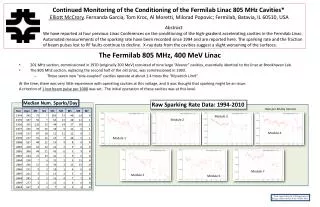
Models and experimental results from LQ, HQ (… and more) and QXF Giorgio AmbrosioFermilab With contributions by: • Helene Felice, ShlomoCaspi, Tiina Salmi, Maxim Martchevsky (LBNL) • GuramChlachidize, Linda Imbasciati (FNAL) • Massimo Sorbi, Lidia Rossi, Vittorio Marinozzi (Univ. of Milan) • Paolo Ferracin, Ezio Todesco, Marta Baiko, Hugo Bajas (CERN) • Giulio Manfreda (Univ. of Udine) WAMSDO CERN January 16, 2013
Outline • What is the maximum acceptable temperature at the hot spot in Nb3Sn accelerator magnets? • What feedback from magnet test to QP codes? • Where does the QXF stand?
maximum acceptable temperature at hot spot?In Nb3Sn accelerator magnets
High Hot-Spot Temperature Test in Quad Test performed on TQS01c (1m quad) • with MJR conductor (47% copper) • Spontaneous quenches (pole turn, inner layer) • same segment during all study; • High MIITs (and Temp) by removing protection features • Iq ~ 80% ssl at start • Iq_max: + 4% • Iq_min: - 25% +3.3% -7.2% +4% -7.4% Fermilab TD Note: TD-07-007: LARP TQS01c Test Summary G. Ambrosio, R. Carcagno, S. Caspi, G. Chlachidze, F. Lewis, A. Lietzke, D. Orris, Y. Pischalnikov, G.L. Sabbi, D. Shpakov, C. Sylvester, M. Tartaglia, J.C. Tompkins, G. Velev, A.V. Zlobin -25%
IEEE TRANSACTIONS ON APPLIED SUPERCONDUCTIVITY, VOL. 18, NO. 2, JUNE 2008 179 Test and Analysis of Technology Quadrupole Shell (TQS) Magnet Models for LARP S. Caspi, G. Ambrosio, A. N. Andreev, E. Barzi, R. Bossert, D. R. Dietderich, P. Ferracin, A. Ghosh, A. R. Hafalia, V. V. Kashikhin, A. F. Lietzke, I. Novitski, G. L. Sabbi, and A. V. Zlobin Fig. 9. Epoxy de-lamination and slight inward cable displacements on one side of coil-15’s inner-pole island after high-MIITs study.
Hot Spot Temperature Computation Hot spot temperature computed with QuenchPro: • MIITs vs. Temperature including epoxy and insulation in enthalpy computation • Adiabatic approximation • Assuming peak field on cable (at quench current) • Constant in QuenchPro • RRR: 130-170 (range of RRR in quenching coil) • RRR of quenching segment not available
Hot Spot Temperature vs. Degradation 403 342 395 370 All temperatures are in K +/- 6 K (for RRR uncertainty) 340 396 280 459 382 543
Tests on Cable Samples and Small Racetrack Peak temperatures measured by resistance growth with voltage taps around hot spot Fig. 6.8: Summary of quench experiments: reduced current (quench current divided by maximum current) vs. peak temperatures reached during the preceding quench test. The lines represent the temporary sequence of the peak temperature events. Degradation of electrical strength http://lss.fnal.gov/archive/thesis/2000/fermilab-thesis-2004-14.pdf Quench Protection Issues of Nb3Sn Superconducting Magnets for Particle Accelerators L. Imbasciati, PhD dissertation
Conclusions - I • T_hot spot > T1 “Active territory”: • Hot spot after quench is not in the same strain/stress state where it was before the quench • Magnet may train, detrain, … effect is reversible • T_hot spot > T2 > T1 “Degradation territory”: • Degradation is irreversible and/or the magnet may experience insulation failures • T1 = 340-370 K based on TQS01C • T1 > 400 K based on results in L. Imbasciati dissertation • Glass Transition temperature of CTD101K = 386 K This may be the physical limit! Max acceptable temperature = 386 K - margin AIP Conf. Proc. 614, pp. 295-304; Highly radiation-resistant vacuum impregnation resin systems for fusion magnet insulation P. E. Fabian, N. A. Munshi, and R. J. Denis and CTD-101K Material datasheet
Conclusions - II Computations may slightly underestimate the hot spot temperature because: • They include epoxy and insulation • They compute “cable average temperature” • Local RRR may be higher (for instance at cable edge) • Material prop. may not be “correct” (for instance G10) • with RRR = 70 the hot spot temperature changes 340 K 383 K Quench Protection Issues of Nb3Sn Superconducting Magnets for Particle Accelerators L. Imbasciati Fig. 6.6: Quench integral accumulated during the quench experiments performed on cables (above), and during the small magnet experiment (below), compared to curves calculated using the heat balance equation including metal components only, with epoxy resin and with 0.15 mm insulation.
Conclusions - III • This picture may change if another material is used for potting: • The glass transition temperature may change • Other mechanisms may cause detraining or degradation • These tests should be repeated on magnet with cored cable • Core and cable may not come back to the same condition after quenches at high temperature, …
Long Quadrupole Main Features: Aperture: 90 mm magnet length: 3.7 m LQ Design Report available online at: https://plone4.fnal.gov/P1/USLARP/MagnetRD/longquad/LQ_DR.pdf
Quench Protection Goal: MIITs < 7.5 Temp ~ 360-370 K (adiabatic approx) Quench protection param. (4.5 K) – conservative hypothesis Dump resistance: 60 mW(extract ~1/3 of the energy; Vleads ~ 800 V) 100% heater coverage ( heaters also on the inner layer) Detection time: ~5 ms based on TQs with I > 80% ssl Heater delay time: 12 ms based on TQs with I > 80% ssl 6 ms (transv. propagation through insul.) + 6 ms (long. propagation btw heating station) Very challenging! J in copper = 2900 A/mm2 at 13.9 kA (4.3 K SSL) LARP Collab. Mtg 10 – Port Jefferson, Apr. 23-25, 2008 Long Quadrupole Overview – G. Ambrosio 14
Measurement vs. Computation • Tests showed that there is margin: • MIITs lower than computed Faster current decay, • With one exception: quench in midplane block at 11.3 kA • RRR higher than value used in computations. Hot spot temperature lower than computed values
Feedback from LQ test • Current decay faster than computed • At very start! • 0 – 10 ms http://tdserver1.fnal.gov/tdlibry/TD-Notes/2012%20Tech%20Notes/TD-12-018.pdf Study of Superconducting-to-Resistive Transition for the US-LARP Large High Field Quadrupoles for the LHC Upgrade Lidia Rossi, Bachelor dissertation
Time constant at current decay start Time constant at decay start: t = L / R with R = Rdump + Rbusbars(Rcoil is negligeable) tmeasured < testimated(240 ms) tmeasuredused to evaluate Leffective
Dynamic Inductance vs. Measurements • Leffective< Ldynamic • Large variation of L with frequency at room temperature • reduction of Leffective due to eddy currents (cable, structure) Dynamic inductance computed by OPERA
New Comparison • Better modeling after including these and other improvements into QuenchPro
“Quench-back” at High Current? Time constant at decay start: t = L / R At Iq/Issl > 88% tmeasured becomes smaller Quench back? Multipole quenches due to current redistribution?
HQ01e – Quench-Back • Magnet sitting at a constant current: from 5 to 13 kA – (NO quench) • Discharge in the 40 mWdump resistor without PH • Does the magnet quench from eddy current generation in the cable (form of quench-back)? • From the current decay: • At 5 and 10 kA: no sign of quench • A 13 kA: signs of quench • At 15 kA: fraction of the magnet is quenching • Last 15 kA test with PH: no clear impact HQ01e at CERN H. Bajas et al., “Test Results of the LARP HQ01 Nb3Sn quadrupole magnet at 1.9 K”, presented at ASC2012 2nd Joint HiLumi LHC - LARP Annual meeting
Conclusions • These features may help the protection, but should be well understood: • Above what Iq/Issl do they have a significant effect? • Effect of cored cable? • Note: maybe a “dump resistor” may help to trigger them even if the energy extracted is no so significant… • Generally speaking: do validation of QP codes with real data!
LQ Coils after Test Delamination on Inner layer Heater – coil Insulation – heater Insulation – coil Also one heater-coil short • Possible causes: • Superfluid helium + quench • Seen in TQ coils • Heat from heaters on ID • Not done in TQ coils • Options: • Strengthen insulation • Not good for cooling • Change heater location • Best solution
Quench Propagation Velocity Measurements at 4.3 K IEEE TRANSACTIONS ON APPLIED SUPERCONDUCTIVITY, VOL. 17, NO. 2, JUNE 2007 Assembly and Tests of SQ02, a Nb3Sn Racetrack Quadrupole Magnet for LARP P. Ferracin, G. Ambrosio, E. Barzi, S. Caspi, D. R. Dietderich, S. Feher, S. A. Gourlay, A. R. Hafalia, C. R. Hannaford, J. Lizarazo, A. F. Lietzke, A. D. McInturff, G. L. Sabbi, and A. V. Zlobin
By Massimo Sorbi, GiulioManfreda, VittorioMarinozzi QXF protection(preliminary results)
ROXIE – QLASA Comparison Comparison btw QLASA and ROXIE using same material properties (MATPRO library) and assumptions: Magnet length: 8.5 m Total stored Energy: 15.2 MJ for Qlasa – 12.2 MJ for Roxie, with the inductance variation Rdump = 58 mohm Vmax = 1000 V (+/- 500 V) Heaters on Inner and Outer layers
Hot Spot Temperature vs. Delay Time 370 Whole magnet should be quenched in less than 45 ms!
Can we achieve this delay timewith heaters only on outer layer? • IL OL • 88 • 22 • 15 15 • 5 • 15 • 5 • __ __ • 30 45 • Delay time after detection = • Validation time + • Switch time + • Heater-coil diffusion time + • Longitudinal propagation btw heating stations • All OuterLayer quenched • Layer-layer diffusion + • Longitudinal propagation • Whole magnet quenched In order to have all magnet quenched in 45 ms:
Preliminary Conclusions • We should calibrate ROXIE and QLASA with experimental results • We should test Nb3Sn magnets with cored cables at high hot spot temperatures • We have to fight for every ms in the design of MQXF and its protection system Together we will make it!