Download
1 / 28
280 likes | 411 Views
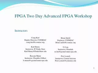
High Speed Digital Systems Lab. Project D02209: FPGA Bridge between Internal & External Networks. Final Presentation October 2011. Supervisor: Mony Orbach Students: Alex Blecherov Eyal Ben Dov Project Period: 2 semesters. High Speed Digital Systems Lab. Motivation.

E N D
High Speed Digital Systems Lab Project D02209:FPGA Bridge between Internal & External Networks Final Presentation October 2011 Supervisor: Mony Orbach Students: Alex Blecherov Eyal Ben Dov Project Period: 2 semesters
High Speed Digital Systems Lab Motivation Utilizing High-speed communication between devices Narrowing the gap between High-speed LAN (via FSB) and External network (via Internet) Demand for reliable and fast communication
High Speed Digital Systems Lab General Conception Assuming there are several different large networks – Internal Networks and External Networks. We wish to create a mutual environment (to act as an accelerator) to provide the ability to communicate between them with high rates and minimal overhead.
High Speed Digital Systems Lab Goals Design & implementation of high speed communication bridge on Xilinx FPGA device (SoPC) Allowing Local and External networks which operate with different protocols and rates to communicate with each other with high reliability Achieving fastest transmission rate possible Explore and expertise a new FPGA device (Virtex 6) & work environment (ISE 13.1)
High Speed Digital Systems Lab Specifications Hardware • Xilinx Virtex-6 ML605 FPGA Evaluation Kit Software • ISE Design Suite Logic Edition Version 13.1 • LogiCore Generator • Xilinx Platform Studio (XPS) • Software Development Kit (SDK) • Wireshark Packet Sniffer
High Speed Digital Systems Lab Possible Solutions Solution 2 Solution 1 Local Fast Networks (up to 5 Gbps) Local Fast Networks (up to 5 Gbps) External Network (TCP/IP) External Network (TCP/IP) Bridge: Virtex 6 ML605 FPGA Bridge: Virtex 6 ML605 FPGA
Chosen Solution High Speed Digital Systems Lab External Network (TCP/IP) Bridge: Virtex 6 ML605 FPGA Local Fast Networks (up to 5 Gbps)
Project Test Bench Diagram High Speed Digital Systems Lab Local Fast Network (up to 5 Gbps) External Network (TCP/IP) Bridge: Virtex 6 ML605 FPGA
Tri Mode Ethernet MAC PacketBased on IEEE Std 802.3 High Speed Digital Systems Lab 64 – 1518 Bytes • Preamble – Exists due to historical reasons,contains the constant pattern 0x55 [optional]. • SFD - Marks the start of the frame, and must contain the value 0xD5. • Destination Address - The LSB determines if the address is an individual/unicast (0) or group/multicast (1) address. • It’s the first field that must always be provided.
Tri Mode Ethernet MAC PacketBased on IEEE Std 802.3 High Speed Digital Systems Lab 64 – 1518 Bytes • Source Address – Must always be provided by the client because it’s not modified by the Ethernet MAC. • Length/Type – If the decimal value of this field is 1536 or greater it’s interpreted as a Type field (Indicates if it’s a VLAN frame or PAUSE/MAC ctrl frame). Otherwise it’s interpreted as a Length field and represents the number of bytes in the following Data field.
Tri Mode Ethernet MAC PacketBased on IEEE Std 802.3 High Speed Digital Systems Lab 64 – 1518 Bytes • Data – Varies from 0-1500 Bytes, must always be provided. • Pad – Used to ensure that the frame length is at least 64 bytes in length, and required for successful CSMA/CD • operation. • FCS - Calculated over the destination address, source address, length/type, data, and pad fields using a 32-bit Cyclic Redundancy Check (CRC). If an incorrect FCS value • is received it indicates that the received frame is bad.
Internet Protocol Suite (TCP/IP) Packet – IETF – RFC 791 High Speed Digital Systems Lab • Version – For IPv4, this has a value of 4. • Internet Header Length (IHL) - Specifies the size of the header (5-15). • Differentiated Services – Type of Service - Indicates how this packet should be treated. • Total Length - Defines the entire datagram size (576 - 65,535Bytes).
Internet Protocol Suite (TCP/IP) Packet – IETF – RFC 791 High Speed Digital Systems Lab • Identification ,Flags & Fragment Offset – Used to handle received fragmented packet. • Time To Live (TTL) - Indicates how many hops are allowed before the packet is discarded. • Protocol - Defines the protocol used in the data portion of the IP datagram
Internet Protocol Suite (TCP/IP) Packet – IETF – RFC 791 High Speed Digital Systems Lab • Header Checksum - Used for error-checking of the header (calculated every hop). • Source & Destination Address – An IPv4 address is a group of four octets for a total of 32 bits. • Options - Additional header fields that may follow the destination address field, but usually not in use.
Overview of the Cores in use High Speed Digital Systems Lab • TEMAC (Tri-Mode Ethernet MAC) - The TEMAC core is designed to the IEEE 802.3 (Ethernet protocol) specification and operates in 1000Mbps, 100 Mbps, and 10 Mbps modes. • We’ll use this core for the External network. • Aurora - A very efficient low-latency protocol that uses the least possible amount of logic while offering excellent performance. • We’ll use this core for the Internal Network (FSB).
Part B Implementation High Speed Digital Systems Lab • Goal: • Create a Bridge module in the Virtex 6 FPGA using the TEMAC and Aurora Cores. • Preserve the internal loopback which was implemented during the first part of the project. • Guiding lines: • The implementation of the Bridge module will be efficient & simple as possible.
Part B Implementation High Speed Digital Systems Lab • Solution: • Creating Protocol translator module with interface to the TEMAC and Aurora Cores, which will be implemented in VHDL and will be based on port forwarding method.
Test Bench Diagram Part A CAT5 Mini USB-USB High Speed Digital Systems Lab
Test Bench Diagram Part B CAT5 Mini USB-USB High Speed Digital Systems Lab SMA connectors Bridge mode
Final Block Diagram High Speed Digital Systems Lab Virtex 6 ML605 Evaluation Board Micro Blaze ExternalNetwork FSB Internal Network SMA Connectors Tx FIFO RJ45 Connector Tri-Mode Embedded Ethernet MAC Protocol Translator TCP/IP - Ethernet Aurora IP Core GTX Transceiver Rx FIFO Ethernet Aurora Protocol
Protocol Translator Implementation High Speed Digital Systems Lab • The functionality of the bridge can be divided into two main flows: • - TX Flow (Internal network sends packets to the external network) • RX Flow (Internal network receives packets from the external network) • The complex flow is the RX flow since the packets needs to be changed.
Packet Analysis High Speed Digital Systems Lab
RX Flow Diagram Wait for Packet High Speed Digital Systems Lab Packet received Packet type = IP no yes Dest. Port in LUT Pass Packet no yes Swap dest. IP & Calc. CHKSUM
Checksum Calculation High Speed Digital Systems Lab Due to changing of the packet’s destination IP address, a new header checksum needs to be calculated in real time. The checksum field is the 16-bit one's complement of the one's complement sum of all 16-bit words in the header. For purposes of computing the checksum, the value of the checksum field is zero.
Checksum Calculation High Speed Digital Systems Lab For example, if the given packet header is: 0x45000030442240008006442e8c7c19acae241e2b (20 bytes) The calculation of the header checksum is: 4500 + 0030 + 4422 + 4000 + 8006 + 0000 + 8c7c + 19ac + ae24 + 1e2b = 2BBCF 2 + BBCF = BBD1 = 1011101111010001 The 1'S of sum = 0100010000101110 = 442E
What’s next? High Speed Digital Systems Lab • Integration of the bridge in a real internal network. • Implementing additional links on the bridge in order to connect to internal switches. • Integration & operating of an entire network.
High Speed Digital Systems Lab Barriers on the Way Upgrade of software versions (ISE) was very problematic without proper backward compatibility. Lack of accessible knowledge on utilizing cores on the new FPGA family. Aurora Core didn’t work properly on the FPGA card.Only after upgrading to version 13.1 of ISE and version 6.2 of the Aurora Core, the example design worked properly. Setting the synthesis level effort is very crucial for successful final design especially timings.
Questions? High Speed Digital Systems Lab