Download
1 / 32
400 likes | 1.73k Views
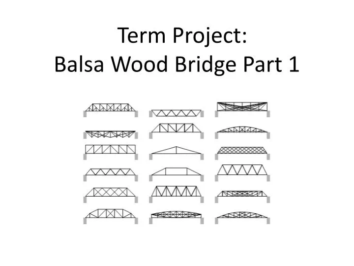
Term Project: Balsa Wood Bridge Part 1. Turning Ideas Into Reality. Engineering Design Process. Read section 2.2, pp. 37-47. What is the difference between an optimist, a pessimist and an engineer?. Optimist: the glass is half full Pessimist: the glass is half empty

E N D
Turning Ideas Into Reality Engineering Design Process Read section 2.2, pp. 37-47
What is the difference between an optimist, a pessimist and an engineer? Optimist: the glass is half full Pessimist: the glass is half empty Engineer: the glass has a 50% overall inefficiency
Engineering Job Functions • Analysis • Design • Test • Development • Sales • Research • Management • Consulting • Teaching In your project you will • “Research” • Design • Analyze • Build • Test • And learn about the engineering design process
you want to build a bridge The Engineering Design Process Span > 30cmMass < 30g made of Balsa etc. Rules • browse web resources • look at Seattle bridges • study rules etc. 1. Customer Needor Opportunity 2. Problem Definition/ Specifications 3. Data and Information Collection 4. Development of Alternative Designs 5. Evaluation of Designs/ Selection of Optimal Design 6. Implementation of Optimal Design Deliverable 1 Analyze Designs (software) Deliverable 2 Build and Test Deliverable 3 Note: this last one is not quite true!
Cautionary Notes: 1. Technically our last step (Testing) would NOT be the implementation. • It would still be part of step 5, finding the optimal design. • We would test and then evaluate the results to optimize. 2. There are different versions of the Engineering Design Process. The one presented here is just one of them.
Example: What went Wrong? The Tacoma Narrows Bridge Disaster
Example: Engineering Design in Action Mars Rover Curiosity in class: 0:00-0:50 and 9:45-16:00 at home: watch the rest (pretty amazing)
What is left today? • rules • some physics without math • deliverables • links • forming teams • materials and logistics Note: the second part of the presentation will cover the software and questions.
Let’s Start the Modeling Software … You can find the software on the project tab of our website: http://seattlecentral.edu/faculty/rheller/Engr110/classproject.html and clicking on Modeling Software Or you can go directly to: http://www.jhu.edu/~virtlab/bridge/truss.htm
How to find the Modeling Software Click on Class Project
How to find the Modeling Software Click on Modeling Software
How to find the Modeling Software Read the instructions Then … To start click on bridge truss
Bridge Terminology • Your bridge will have • Two trusses • Joints or Nodes • Members • One fixed node • One horizontal rolling node • Loads (at least one)
What does the software do? For a given LOAD the software will calculate the FORCE(compressive or tensile) in each member. The software can only do this if you follow the RULES
Bridge Rules • Your bridge MUST have • One fixed node • One horizontal rolling node • Loads (at least one) • And (most importantly) … N= # of nodes (including the support nodes) M= # of members
How many members? M = 7 How many nodes? N = 5 M + 3 = 2 N 7 + 3 = 2 x 5
Why? • To find out take STATICS, Engr214 (offered in fall) • Statically determinate system
Modeling a Bridge Step 1: Start with NODES
Modeling a Bridge Step 2: Convert one node to fixed node and one to horizontal, rolling node
Note on fixed and rolling nodes • You have to first create a node. • Then you select ‘fixed node’ and click on the node you want to be fixed. • You cannot click on fixed node directly.
Modeling a Bridge Step 3: Add members
Modeling a Bridge How many members? How many nodes? M + 3 = 2 N 14 + 3 = 2 x 9 17 = 18 (oops)
Modeling a Bridge Add a load … … or better two Error Message
Modeling a Bridge – Correct version How many members? How many nodes? M + 3 = 2 N 15 + 3 = 2 x 9 18 = 18
Modeling a Bridge – Correct version Click on Calculate Then click anywhere on the grid …
What does this mean? Find the total load: Find the member under the highest compression: Find the member under the highest tension:
What are you looking for? • Note: the loads are relative. Doubling the load will double all forces. • For a given load, you want the maximum compressive and tensile forces to be as small as possible. • If the material behaves better under tension, then your tensile forces can be a little higher.
Let’s Form Teams • Find a team member. • Make sure you have matching schedules. • Exchange email and phone info. • When you have a partner, come to me and I will write down your names. Have fun!