Download
1 / 39
390 likes | 393 Views
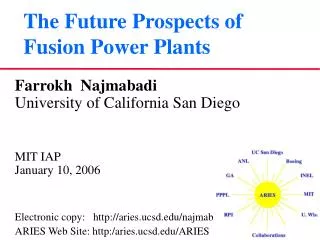
SOFE Mini-Course Fusion Power Plants. Farrokh Najmabadi Prof. of Electrical Engineering Director of Center for Energy Research UC San Diego June 5, 2009. D + T 4 He (3.5 MeV) + n (14 MeV). n. T. n + 6 Li 4 He (2 MeV) + T (2.7 MeV).

E N D
SOFE Mini-CourseFusion Power Plants Farrokh Najmabadi Prof. of Electrical Engineering Director of Center for Energy Research UC San Diego June 5, 2009
D + T 4He (3.5 MeV) + n (14 MeV) n T n + 6Li 4He (2 MeV) + T (2.7 MeV) D + 6Li 2 4He + 3.5 MeV (Plasma) + 17 MeV (Blanket) Fusion is one of very few non-carbon based energy options • DT fusion has the largest cross section and lowest temperature (~100M oC). But, it is still a high-temperature plasma! • Plasma should be surrounded by a Li-containing blanket to generate T. Or, DT fusion turns its waste (neutrons) into fuel! • Through careful design, only a small fraction of neutrons are absorbed in structure and induce radioactivity. • For liquid coolant/breeders (e.g., Li, LiPb), most of fusion energy is directly deposited in the coolant simplifying energy recovery • Practically no resource limit (1011 TWy D; 104 (108) TWy 6Li)
Fusion Energy Requirements: • Confining the plasma so that alpha particles sustain fusion burn • Lawson Criteria: ntE ~ 1021 s/m3 • Heating the plasma for fusion reactions to occur • to 100 Million Celsius (routinely done in present experiments) • Optimizing plasma confinement device to minimize the cost • Smaller devices • Cheaper systems, e.g., lower-field magnets (MFE) or lower-power lasers (IFE) • Extracting the fusion power and breeding tritium • Developing power extraction technology that can operate in fusion environment • Co-existence of a hot plasma with material interface
Fusion Energy Requirements: • Confining the plasma so that alpha particles sustain fusion burn • Lawson Criteria: ntE ~ 1021 s/m3 • Heating the plasma for fusion reactions to occur • to 100 Million oC (routinely done in present experiments) • Optimizing plasma confinement device to minimize the cost • Smaller devices • Cheaper systems, e.g., lower-field magnets (MFE) or lower-power lasers (IFE) • Extracting the fusion power and breeding tritium • Developing power extraction technology that can operate in fusion environment • Co-existence of a hot plasma with material interface
Two Approaches to Fusion Power – 1) Inertial Fusion • Inertial Fusion Energy (IFE) • Fast implosion of high-density DT capsules by laser or particle beams (~30 fold radial convergence, heating to fusion temperature). • A DT burn front is generated, fusing ~1/3 of fuel (to be demonstrated in National Ignition Facility in Lawrence Livermore National Lab). • Several ~300 MJ explosions per second with large gain (fusion power/input power).
Two Approaches to Fusion Power –2) Magnetic Fusion • Magnetic Fusion Energy (MFE) • Particles confined within a “toroidal magnetic bottle” for 10’s km and 100’s of collisions per fusion event. • Strong magnetic pressure (100’s atm) to confine a low density but high pressure (10’s atm) plasma. • At sufficient plasma pressure and “confinement time”, the 4He power deposited in the plasma sustains fusion condition. • Rest of the Talk is focused on MFE
Plasma behavior is dominated by “collective” effects • Pressure balance (equilibrium) does not guaranty stability. • Example: Interchange stability Outside part of torus inside part of torus Fluid Interchange Instability • Impossible to design a “toroidal magnetic bottle” with good curvatures everywhere. • Fortunately, because of high speed of particles, an “averaged” good curvature is sufficient.
Tokamak is the most successful concept for plasma confinement DIII-D, General Atomics Largest US tokamak • Many other configurations possible depending on the value and profile of “q” and how it is generated (internally or externally) R=1.7 m
Portfolio of MFE Configurations Externally Controlled Self Organized Example: Field-reversed Configuration Confinement field generated mainly by currents in the plasma Poloidal field >> Toroidal field Small aspect ratio Simpler geometry Example: Stellarator Confinement field generated by mainly external coils Toroidal field >> Poloidal field Large aspect ratio More stable, better confinement
T3 Tokamak achieved the first high temperature (10 M oC) plasma 0.06 MA Plasma Current R=1 m
JET is currently the largest tokamak in the world ITER Burning plasma experiment (under construction) R=6 m R=3 m
Fusion triple product n (1021 m-3) t(s) T(keV) Progress in plasma confinement has been impressive ITER Burning plasma experiment 500 MW of fusion Power for 300s Construction will be started shortly in France
Large amount of fusion power has also been produced ITER Burning plasma experiment DT Experiments DD Experiments
Fusion Energy Requirements: • Confining the plasma so that alpha particles sustain fusion burn • Lawson Criteria: ntE ~ 1021 s/m3 • Heating the plasma for fusion reactions to occur • to 100 Million oC (routinely done in present experiments) • Optimizing plasma confinement device to minimize the cost • Smaller devices • Cheaper systems, e.g., lower-field magnets (MFE) or lower-power lasers (IFE) • Extracting the fusion power and breeding tritium • Developing power extraction technology that can operate in fusion environment • Co-existence of a hot plasma with material interface
Plasma is heated to fusion temperatures routinely in current experiments Heating Methods (See ITER talk for state-of-the-art hardware): • Neutral Particle beams • Neutral particles can cross the magnet field and enter the plasma. • Neutral beam particles ionize in the plasma and deposit their energy. • Electro-magnetic waves: • EM waves can transfer energy to electrons or ions through cyclotron resonance or matching of the phase velocity of the wave with particle velocity. • Plasma is a dielectric media and the type of EM wave used depends on plasma parameters and B field to ensure wave propagation and efficient heating. • Frequency range from 10’s of MHz (radio transmitter) to ~100 GHz (gyrotron). • Ohmic heating and plasma compression
Fusion Energy Requirements: • Confining the plasma so that alpha particles sustain fusion burn • Lawson Criteria: ntE ~ 1021 s/m3 • Heating the plasma for fusion reactions to occur • to 100 Million oC (routinely done in present experiments) • Optimizing plasma confinement device to minimize the cost • Smaller devices • Cheaper systems, e.g., lower-field magnets (MFE) or lower-power lasers (IFE) • Extracting the fusion power and breeding tritium • Developing power extraction technology that can operate in fusion environment • Co-existence of a hot plasma with material interface
We have made tremendous progress in optimizing fusion plasmas • Substantial improvement in plasma performance though optimization of plasma shape, profiles, and feedback. • Achieving plasma stability at high plasma pressure. • Achieving improved plasma confinement through suppression of plasma turbulence, the “transport barrier.” • Progress toward steady-state operation through minimization of power needed to maintain plasma current through profile control. • Controlling the boundary layer between plasma and vessel wall to avoid localized particle and heat loads.
Fusion Energy Requirements: • Confining the plasma so that alpha particles sustain fusion burn • Lawson Criteria: ntE ~ 1021 s/m3 • Heating the plasma for fusion reactions to occur • to 100 Million oC (routinely done in present experiments) • Optimizing plasma confinement device to minimize the cost • Smaller devices • Cheaper systems, e.g., lower-field magnets (MFE) or lower-power lasers (IFE) • Extracting the fusion power and breeding tritium • Developing power extraction technology that can operate in fusion environment • Co-existence of a hot plasma with material interface
DT Fusion requires a T breeding blanket • Requirement: Plasma should be surrounded by a blanket containing Li D + T He + n n + 6Li T + He • Through careful design, only a small fraction of neutrons are absorbed in structure and induce radioactivity • Rad-waste depends on the choice of material: Low-activation material • Rad-waste generated in DT fusion is similar to advanced fuels (D-3He) • For liquid coolant/breeders (e.g., Li, LiPb), most of fusion energy (carried by neutrons) is directly deposited in the coolant simplifying energy recovery • Issue: Large flux of neutrons through the first wall and blanket: • Need to develop radiation-resistant, low-activation material: • Different from fission material because the high energy fusion neutron generates H and He in addition to displacement damage.
New structural material should be developed for fusion application • Fe-9Cr steels: builds upon 9Cr-1Mo industrial experience and materials database • (9-12 Cr ODS steels are a higher temperature future option) • V-4Cr-4Ti: Higher temperature capability, targeted for Li self-cooled blanket designs • SiC/SiC: High risk, high performance option (early in its development path) • W alloys: High performance option for PFCs (early in its development path)
Managing the plasma material interface is challenging Flux surface Confined plasma • Alpha power and alpha ash has to eventually leave the plasma • Particle and energy flux on the material surrounding the plasma • Modern tokomaks use divertors: • Closed flux surfaces containing hot core plasma • Open flux surfaces containing cold plasma diverted away from the first wall. • Particle flux on the first wall is reduced, heat flux on the first wall is mainly due to radiation (bremsstrahlung, synchrotron, etc.) • Alpha ash is pumped out in the divertor region • High heat and particle fluxes on the divertor plates. First Wall Separatrix Edge Plasma Divertor plates
Fusion physics & technology Low-activation material Elements of the case for fusion power were developed through interaction with representatives of U.S. Electric utilities and energy industry • Have an economically competitive life-cycle cost of electricity • Gain Public acceptance by having excellent safety and environmental characteristics • No disturbance of public’s day-to-day activities • No local or global atmospheric impact • No need for evacuation plan • No high-level waste • Ease of licensing • Reliable, available, and stable as an electrical power source • Have operational reliability and high availability • Closed, on-site fuel cycle • High fuel availability • Capable of partial load operation • Available in a range of unit sizes
Increase Power Density (1/Vp) What we pay for,VFPC • Little Gain Big Win D r r > D r ~ D r < D Decrease Recirculating Power Fraction Cost of power plant is correlated to Machine size and the recirculating power • Improvement “saturates” at ~5 MW/m2 peak wall loading (for a 1GWe plant). • A steady-state, first stability device with Nb3Sn technology has a power density about 1/3 of this goal. Mass power density= net electric output / mass of fusion core QE = net electric output / recirculating electric power • Improvement “saturates” about Qplasma ~ 40. • A steady-state, first stability device with Nb3Sn Tech. has a recirculating fraction about 1/2 of this goal.
COE insensitive of power density COE insensitive of current drive Evolution of ARIES Tokamak Designs
Pulsar (pulsed-tokamak): • Trade-off of b with bootstrap • Expensive PF system, under-performing TF “Conventional” Pulsed plasma: Explore burn physics (ITER) • ARIES-I (first-stability steady-state): • Trade-off of b with bootstrap • High-field magnets to compensate for low b Demonstrate steady-state first-stability operation. (ITER) • Explore reversed-shear plasma • Higher Q plasmas • At steady state Explore envelopes of steady-state reversed-shear operation Continuity of ARIES Research Has Led to the Progressive Refinement of Plasma Optimization • ARIES-RS (reverse shear): • Improvement in b and current-drive power • Approaching COE insensitive of current drive • ARIES-AT (aggressive reverse shear): • Approaching COE insensitive of power density • High b is used to reduce toroidal field
ITER and satellite tokamaks will provide the necessary data for a fusion power plant DIII-D DIII-D ITER Simultaneous Max Baseline ARIES-AT Major toroidal radius (m) 1.7 1.7 6.2 5.2 Plasma Current (MA) 2.25 3.0 15 13 Magnetic field (T) 2 2 5.3 6.0 Electron temperature (keV) 7.5* 16* 8.9** 18** Ion Temperature (keV) 18* 27* 8.1** 18** Density (1020 m-3) 1.0* 1.7* 1.0** 2.2** Confinement time (s) 0.4 0.5 3.7 1.7 Normalized confinement, H89 4.5 4.5 2 2.7 b (plasma/magnetic pressure) 6.7% 13% 2.5% 9.2% Normalized b 3.9 6.0 1.8 5.4 Fusion Power (MW) 500 1,755 Pulse length 300 S.S. * Peak value, **Average Value
ARIES-AT is an attractive vision for fusion with a reasonable extrapolation in physics & technology • Low level waste; • Public & worker safety; • High availability. • Competitive cost of electricity (5c/kWh); • Steady-state operation;
ARIES-AT features a high-performance blanket Outboard blanket & first wall • Simple, low pressure design with SiC structure and LiPb coolant and breeder. • Innovative design leads to high LiPb outlet temperature (~1,100oC) while keeping SiC structure temperature below 1,000oC leading to a high thermal efficiency of ~ 60%. • Simple manufacturing technique. • Very low afterheat. • Class C waste by a wide margin.
PbLi Inlet Temp. = 764 °C Max. SiC/SiC Temp. = 996°C Max. SiC/PbLi Interf. Temp. = 994 °C Bottom Top PbLi Outlet Temp. = 1100 °C Design leads to a LiPb Outlet Temperature of 1,100oC While Keeping SiC Temperature Below 1,000oC • Two-pass PbLi flow, first pass to cool SiCf/SiC box second pass to superheat PbLi
Dual coolant with a self-cooled PbLi zone, He-cooled RAFS structure and SiC insert • Flow configuration allows for a coolant outlet temperature to be higher than maximum structure temperature
Gad-cooled W divertor designs with capability of 10-12MW/m2 has been produced. ARIES-CS T-Tube concept
The ARIES-AT utilizes an efficient superconducting magnet design • On-axis toroidal field: 6 T • Peak field at TF coil: 11.4 T • TF Structure: Caps and straps support loads without inter-coil structure; Superconducting Material • Either LTC superconductor (Nb3Sn and NbTi) or HTC • Structural Plates with grooves for winding only the conductor.
Modular sector maintenance enables high availability • Full sectors removed horizontally on rails • Transport through maintenance corridors to hot cells • Estimated maintenance time < 4 weeks ARIES-AT elevation view
Blanket 1 (replaceable) Blanket 2 (lifetime) Shield (lifetime) • Only “blanket-1” and divertors are replaced every 5 years Fusion Core Is Segmented to Minimize the Rad-Waste
After 100 years, only 10,000 Curies of radioactivity remain in the 585 tonne ARIES-RS fusion core. Radioactivity levels in fusion power plantsare very low and decay rapidly after shutdown • SiC composites lead to a very low activation and afterheat. • All components of ARIES-AT qualify for Class-C disposal under NRC and Fetter Limits. 90% of components qualify for Class-A waste. Ferritic Steel Vanadium Level in Coal Ash
Waste volume is not large • 1270 m3 of Waste is generated after 40 full-power year (FPY) of operation. • Coolant is reused in other power plants • 29 m3 every 4 years (component replacement), 993 m3 at end of service • Equivalent to ~ 30 m3 of waste per FPY • Effective annual waste can be reduced by increasing plant service life. • 90% of waste qualifies for Class A disposal
In Summary: • Over 15 MW of fusion power is generated (JET, 1997) establishing “scientific feasibility” of fusion power • Although fusion power < input power. • ITER will demonstrate “technical feasibility” of fusion power by generating copious amount of fusion power (500MW for 300s) with fusion power > 10 input power. • Tremendous progress in understanding plasmas has helped optimize plasma performance considerably. • Vision of attractive fusion power plants exists. • Transformation of fusion into a power plant requires considerable R&D in material and fusion nuclear technologies