Download

1 / 14
140 likes | 230 Views
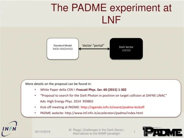
Results of the radioactive source scan of the first 17 MWPC produced at LNF. Davide Pinci on behalf of the LNF-Roma1 MWPC group. System layout. 137 Cs source case. Gap A Gap B Gap C Gap D. Gas in. Gas out. HV. We measure the current drawing in the HV channels in 3x53=159 positions.

E N D
Results of the radioactive source scan of the first 17 MWPC produced at LNF Davide Pinci on behalf of the LNF-Roma1 MWPC group
System layout 137Cs source case Gap A Gap B Gap C Gap D Gas in Gas out HV We measure the current drawing in the HV channels in 3x53=159 positions
Photon flux profile We recorded the current increase while the source was approaching the first pad edge No significant illumination differences among the gaps 15 cm Photon flux diameter of about 15 cm
Hv and ground connections check Althuogh the beam flux has a 15 cm diameter, the system can give very precise information A 2.75 cm pad disconnected from ground A wire pad (13 wires x 2 mm pitch) disconnected from HV
Uniformity inside the gaps The requirement is to have on the 95% of the gap area a current in the range: C0/1.25 and C0x1.25 The gap uniformity is going better. The behaviour of Chamber C012 could be very interesting to be studied Area in the 0.8-1.25 range (%) Chamber number
Gap C Gap D Double-gap CD Chamber C012 A bent panel between gaps C and D provides this situation: the gain in the gap C and D not uniform... ... while the gain of the Bi-Gap CD is rather flat. What about efficiency, time resolution and cluster size? ... to be investigated with test beam or cosmic rays...
Uniformity inside the Bi-Gaps The situation of C012 is similar to other chambers (e.g.....) We decided to study the Bi-Gap uniformity too. The Bi-Gap uniformity is better than the single Gap one. Limit of 95% Area in the 0.8-1.25 range (%) Some mechanics problems (e.g. bent panels) turn out to compensate. We should study the performance of these chambers in order to get a decision on the quality assessment. Chamber number
190 nA x 1.25 = 240 nA Mean value = 190 nA 190 nA : 1.25 = 152 nA Uniformity between different gaps Here are the average values of the 159 current measurements made in each gap The production procedure has being optimized (mainly on the basis of the source scan feedback) Average current (nA) After some bugs have been fixed the quality seems to converge to a good level. Gap A = 172 23 nA Gap B = 192 28 nA Gap C = 212 24 nA Gap D = 186 28 nA No systematic effects. Chamber number
All the gaps together In the whole checked production (17 chambers) 8 gaps out of the allowed range In the last 10 chambers no one gap found out of the allowed range 240 nA 152 nA
HV distribution proposal • On the experiment we will have a large number of indipendent HV channels. We can think to a smart HV distribution to equilize the gap gains. • Our proposal, for istance, is to divide the gaps in 5 gain Classes (+ the “Hospital”): • where G0 is the nominal gain and D has to be chosen on the basis of the production quality. • The HV channels will be also divided in 5 Classes (+ 1 for the “Hospital”) which will provide 5 (+1) HV values. • I tried to apply this scheme to the current situation. • resulted to be 36 nA/190 nA, hence 20% of the nominal gain. The HV values would be:
190 nA x 1.25 = 240 nA Mean value = 190 nA 190 nA : 1.25 = 152 nA The optimized situation Here are the average values of the 159 current measurements made in each gap Average current (nA) Chamber number
The gain distributions With an optimized HV distribution in the current situation it would be possible to reduce the maximum gain spread from 170 nA (i. e. the 90% of the mean value) to 48 nA (i. e. the 25%). We think it could be very usefull to understand the feasibility of such a HV scheme.
Future developments So far we are not able to take into account the ambiental condition: • we measure the atmosferic pressure with a too low resolution (1 mbar); • we don’t measure the gas temperature inside the chamber; The idea is to build a single MWP gap to be placed on the table, under the chamber in test and to use as a monitor. The cosmic ray station is ready to acquire up to 128 MWPC pads. Waiting for the Mux, we will add 3x32 TDC Ch and we can start to investigate some regions of the most interesting chambers (e.g. C012).
Systematic differences between gaps Gap A + Gap B = 364 nA Gap C + Gap D = 396 nA Average gain (nA) Average gain (nA) Average gain (nA) Average gain (nA)