Download
1 / 22
220 likes | 231 Views
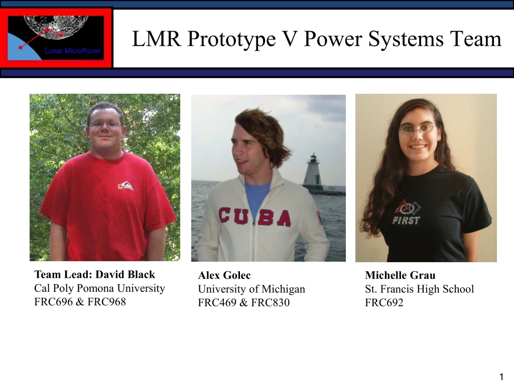
LMR Prototype V Power Systems Team. Team Lead: David Black Cal Poly Pomona University FRC696 & FRC968. Alex Golec University of Michigan FRC469 & FRC830. Michelle Grau St. Francis High School FRC692. LMR Power System Requirements Previous Prototype Capability Prototype 5 Goals

E N D
LMR Prototype V Power Systems Team Team Lead: David Black Cal Poly Pomona University FRC696 & FRC968 Alex Golec University of Michigan FRC469 & FRC830 Michelle Grau St. Francis High School FRC692
LMR Power System Requirements • Previous Prototype Capability • Prototype 5 Goals • Prototype 5 Power System Hardware • - Wiring Block Diagram • - Solar Panel • - On-board charging and protection circuitry • - Lithium-Ion Battery • - Battery Thermal and Vibration Isolation • - Voltage and Current Monitoring Circuitry • - Shutdown and Wake Circuitry • - Regulated Power Supply • Cost • Battery Testing LMR Prototype V Power System Outline
LMR Power System Requirements • Provide capability for a 120 minute all-systems-active mission duration • Provide approx. 24VDC to motor controls, and regulated 12VDC and 5VDC to onboard devices • Provide means for umbilical power • Maximum battery mass: 1.1kg • Maximum battery volume 12.5cm x 8.0cm x 7.0cm
Previous LMR Prototype Capability • Battery consisted of three six-cell NiMH “stick packs” in series • 21.6V fully charged, 3300mAh, < 70 Watt-Hours of capacity, 1.1kg • 40-minute mission duration • Low power density, high self-discharge rate: 30% per month • No voltage and current monitoring feedback • No onboard charging circuitry • One-time mission
Prototype V Power System Goals • Meet original LMR Power System Requirements - 120-minute mission duration • Implement lithium-ion battery technology • Implement onboard charging circuitry • Provide voltage and current feedback to CPU • Provide capability for subsequent missions by means of complete shutdown and solar recharging • Perform various lithium-ion battery testing
Prototype V Power System Hardware – Solar Panel • Spectrolab GaInP2/GaAs/Ge Dual-Junction photovoltaic cells • 21.5% Minimum Average Efficiency • Five 3cm x 7cm cells in series • Measured on Earth: 11.5Voc , 2.2W max • Estimated max output on moon: 3.0W • Est. time to fully recharge on moon: - 4 days in full overhead sun • Future Prototypes: larger solar arrays, higher efficiency (29%) cells, faster recharging
Prototype V Power System Hardware –Onboard Charging and Protection Circuitry • Custom developed fully automatic embedded 6-cell lithium charging and protection circuit • 7.1cm x 9.5cm x 1.9cm • Accepts external 26-28V input from lander, or solar input from onboard panel (via DC-DC conversion) • Monitors pack voltage during charge and switches from constant- • current to constant-voltage mode for increased charge capacity • Monitors pack temperature and terminates charging if temperature • goes out of range • Protection circuit monitors cell voltages and disconnects battery if • cells fall out of 3.00V to 4.35V range; prevents irreversible deep • discharge damage
Prototype V Power System Hardware – Lithium-Ion Battery • Custom assembled using readily- available, robust 18650 form-factor cells • Suitable for use in vacuum environment • High energy density - tested 140 Watt-hour capacity* • 12.0cm x 7.5cm x 5.0cm, 862 grams • 18 cells in 6S3P configuration • 22.2V nominal voltage • Low self-discharge rate: 5% per month • Teflon-insulated wiring • Future considerations: space-ready assembly methods – hypersonic welding, rigid mounting for each cell *At average 62W discharge, 24 degrees C.
Prototype V Power System Hardware –Battery Thermal and Vibration Isolation • Silicone foam rubber – 1/8” thick • Retains properties over -75 to 232 °C range • Excellent resistance to heat and vibration transfer
Prototype V Power System Hardware –Voltage and Current Monitoring Circuitry • 7.1cm x 4.0cm x 1.1cm • Programmable PIC microcontroller based design • Monitors total pack voltage and total current draw (up to 4A continuous, 7A peak) during use, and reports to CPU over USB interface • Possible future expansion: individual device current monitoring and reporting
Prototype V Power System Hardware –Shutdown and Wake Circuitry • 7.1cm x 4.0cm x 1.1cm • Ultra-low power consumption: < 1mA • Programmable PIC microcontroller based design allows for future customization • Monitors pack voltage. Sends “impending shutdown” GPIO signal to CPU at 20.25V • High-current-capacity load-switching transistors cut power to motor controls and regulated power supply at 18.5V and remain shut off until battery is fully recharged • Possible future expansion: Programmable by rover CPU prior to shutdown, multiple independent load switching, timer based shutdown and wake, etc.
Prototype V Power System Hardware –Regulated Power Supply • RTD Embedded Technologies XPWR104HR 75W power supply • PC/104 form factor • 8-36V input range • Regulated 12V and 5V output • -40 to +85°C operation • Short-circuit protection
Lithium-Ion Battery Testing • Performed a variety of tests on prismatic and 18650 cylindrical Li-Ion cells • Charge and discharge rate testing • Thermal testing • Comparison between manufacturers
LMR Prototype V Power System - Conclusions • Met the 120-minute run time requirement • Met the volume and mass requirements • Achieved self-recharging via solar power • Provided much-enhanced power circuitry over previous rover prototype • No significant temperature increase during charging, but temperature does increase somewhat while discharging • Cells perform better at higher temperatures, and exhibit self-warming in cold environment • Cells from certain manufacturers may be over-rated in capacity
LMR Prototype 5 Power System Questions?