Download
1 / 48
490 likes | 503 Views
Design of Lateral Load Resisting Frames Using Steel Joists and Joist Girders. Authored by James M. Fisher, Ph.D., P.E. Perry S. Green, Ph.D. Joseph J. Pote, P.E. Presentation by: James M. Fisher, Ph. D., P. E. Vice President Computerized Structural Design Milwaukee, WI.

E N D
Design of Lateral Load Resisting Frames Using Steel Joists and Joist Girders Authored by James M. Fisher, Ph.D., P.E. Perry S. Green, Ph.D. Joseph J. Pote, P.E. Presentation by: James M. Fisher, Ph. D., P. E. Vice President Computerized Structural Design Milwaukee, WI
Technical Digest No. 11 • The purpose of TD No. 11 is to present information to the EOR, and the joist manufacturer, for the design of single story moment resisting joist and Joist Girder frames. • Design considerations for both wind and seismic lateral loads are presented.
Technical Digest No. 11 • The digest has been limited to single story frames, not because of wind requirements, but because of current requirements for seismic design; in particular, the use of strong beam, weak column systems which are typically necessary when using truss construction in lieu of beams and girders.
Technical Digest No. 11 • The Digest illustrates procedures to: • Analyze, • Design, and • Specify joist and Joist Girder moment frames to resist wind and seismic lateral loads. • The reader is assumed to be familiar with: • 2005 AISC Specification for Structural Steel Buildings • 2005 AISC Seismic Provisions for Structural Steel Buildings • ASCE 7-05
Technical Digest No. 11 • Designing joist and Joist Girder structures as rigid frames is no more difficult than designing rigid frames with wide flange beams and columns. • To obtain a cost effective design the engineer must be aware of the inter-relationships between framing elements, i.e. joists, Joist Girders, columns, bracing members and connections. • In general, the most economical design is one which minimizes manufacturing and erection costs, and one which reduces the special requirements (seat stiffeners, chord reinforcing, etc.) for the joists, Joist Girders and columns.
Design Methodology • The first consideration relative to the design of the structure is to determine if rigid frame action is required. • For single story structures the optimum framing system generally consists of braced frames in both directions, and the use of a roof diaphragm system to transfer wind and seismic loads to the vertical bracing elements.
Design Methodology • The specifying professional and the joist manufacturer must communicate design data and information to each other. • The specifying professional must specify the necessary loading and stiffness data to the joist manufacturer. • The specifying professional must indicate the type of joist to column connections so that the joist manufacturer can provide the joists with the geometry that meets the design intent. • Dialog must occur between all involved parties prior to final pricing and design.
Design Methodology • The joist manufacturer must design the joists in conformance with the SJI Specifications and other contract requirements specified by the specifying professional.
Analysis Requirements • Forces and moments in single story joist rigid frames are determined in a manner similar to other Ordinary Moment Frames (OMF). • The first step is to perform a preliminary analysis. • In general, it is suggested that the OMF be considered as a pinned based frame to eliminate moment resisting foundations; however, for drift control partially restrained or fixed bases can be considered.
Analysis Requirements • After selecting trial member sizes for the columns and joists, a computer analysis is performed to determine forces, moments, and deflections (both first-order and second-order) for the load combinations prescribed by the Applicable Building Code. • Because a second-order analysis is a non-linear problem, the analysis must be performed for each required load combination.
Frame Model Model for IBC or ASCE Load Combinations
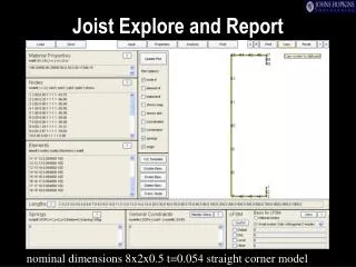
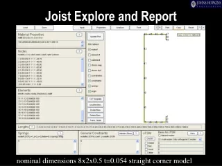
Analysis Trial joist stiffness can be obtained from the SJI equations for the approximate moment of inertia for a joist or a Joist Girder. The SJI equation for a Joist Girder equals 0.018NPLd (LRFD), and 0.027NPLd (ASD) where: N = number of panel points P = panel point load (kips) at factored load level for LRFD, and at nominal load level for ASD L = girder length (ft.) d = girder depth (inches)
Analysis The SJI equation for the approximate moment of inertia for a joist equals 26.767(WLL)(L3)(10-6) for both LRFD and ASD. where: WLL = The RED figure in the K-, LH-, and DLH-Series Load Tables L = (Span – 0.33) in feet for K-Series joists L = (Clear span + 0.67) in feet for LH- and DLH-Series joists
Frame Model Model for AISC-Strong Beam, Weak Column
Specification of Required Forces and Moments • IBC LRFD load combinations are used. • Nominal loads: • D = 15 psf • L = 20 psf (reducible) • S = 5 psf • W (uplift gross) = 27.25 psf (windward roof) = 17.3 psf (leeward roof)
Specification of Required Forces and Moments • Seismic Criteria: • R = 3.5 for OMF • SDS = 0.9297g • SD1 = 0.39g • r = 1.0 • QE = 49 kips • Imin = 6790 in.4 for the exterior girders and 4570 in.4 for the interior girder (analysis requirements). • Minimum width of top chord = 7.0 in. (weld requirements).
Specification of Required Forces and Moments • Minimum thickness of bottom chord = 3/8 in. (weld requirements). • All top chord axial loads and end moments are transmitted directly into the columns via the tie plates. No horizontal forces are transferred through the girder seats. • Chord splices must conform to the requirements of the 2005 AISC Seismic Provisions, Section 7.3a. • Controlling IBC Load Combinations are given below for Joist Girder Mark Numbers G1 and G2, respectively:
+ + + Controlling IBC Load Combinations
2005 AISC Seismic Provisions Section 5.1 • Designation of the seismic load resisting system (SLRS) • Designation of the members and connections that are a part of the SLRS • Configuration of the connections • Connection material specifications and sizes • Locations of demand critical welds • Locations and dimensionsof protected zones • Welding requirements as specified in Appendix W, Section W2.1
Example 1 • The building is located in Charleston, South Carolina. The building code to be used is 2006 International Building Code (IBC 2006). • The precast concrete shear walls at the north and south ends of the building are non-load bearing shear walls, and are used to resist the forces between the first interior rigid frame and the end wall.
Example 1 Loading requirements are specified as: Roof Loads: Dead Load: 1 psf Membrane 2 psf Deck 2 psf Insulation 3 psf Joists and Bridging 2 psf Girder 10 psf Total
Example 1 Collateral Load: 3 psf Sprinkler 2 psf Mechanical & Lighting 5 psf Total Live Load: 20 psf Reducible per Code (12 psf on Joist Girders) Ground Snow Load = 5 psf Roof Snow Load = 5 psf (ASCE 7, Section 7.3, low slope roof criteria)
Example 2 • Wind Load = 120 MPH – Exposure C • Seismic Load: Charleston, South Carolina • Serviceability Requirement: • Maximum drift = H/100 (10 year wind)
Examples 1 and 2 Comparison • Example 1: Charleston, SC • Wind Base Shear (120 mph) • 22.9 kips per frame line (Factored by 1.6) • Seismic Base Shear (R=3.5) • 49.0 kips per frame line • Example 2: Jackson, MS • Wind Base Shear (120 mph) • 22.9 kips per frame line (Factored by 1.6) • Seismic Base Shear (R=3.0) • 14.3 kips per frame line
Examples 1 and 2 Comparison • Example 1 (120 mph, SDC D) • Columns: Exterior W18x86, Interior W18x97 • Total Column Weight = 12,200 lbs • Girder Weight = 6,300 lbs • Total Weight = 18,500 lbs per bay • Example 2 (120 mph, SDC B) • Columns: Exterior W21x111, Interior HSS 8x8x3/16 • Total Column Weight = 8700 lbs • Girder Weight = 3200 lbs • Total Weight = 11,900 lbs per bay
Appendix A • Appendix A contains a complete design of the Joist Girders for Example 1
Acknowledgement • The authors of Technical Digest 11 would like to thank: • The Engineering Practice Committee and the Research Committee of the Steel Joist Institute for their review and contributions to the writing of this document. • John A. Rolfes, S.E., P.E. Vice President of Computerized Structural Design for his assistance in the preparation of the digest, and James O. Malley, S.E. Senior Principal,Degenkolb Engineers, for his insightful review of the digest.