Download

1 / 34
340 likes | 380 Views
Active Suspension System. Students: Caleb Dell, Leslie Garcia, Alex Jaeger Advisors: Prof. Jing Wang, Prof. S. D. Gutschlag. Outline. Project Summary Previous Work System Block-Diagram Component Descriptions Functional Descriptions Work Completed Future Work References Questions.

E N D
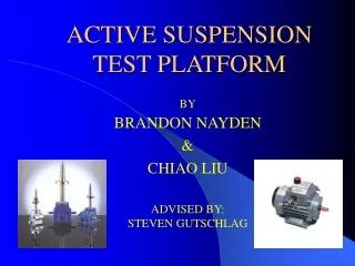
Active Suspension System Students: Caleb Dell, Leslie Garcia, Alex Jaeger Advisors: Prof. Jing Wang, Prof. S. D. Gutschlag
Outline • Project Summary • Previous Work • System Block-Diagram • Component Descriptions • Functional Descriptions • Work Completed • Future Work • References • Questions
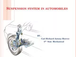
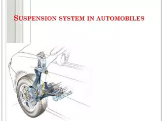
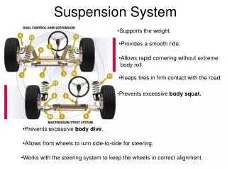
Project Summary • Goal • Design a system to minimize vertical disturbance of a suspended body • Application • Provide a gentle ride to passengers by removing disturbances imparted to a vehicle due to uneven terrain • Apparatus Description: • Lower Platform • Linear Actuator • H-bridge • Microcontroller • Upper Platform • Position Sensor
Previous Work • 1990-1991 Team • Constructed apparatus • 2006-2007 Team • Replaced pneumatic cylinder with an electric linear actuator
Previous Work: 2016-17 team • Organized H-bridge and associated electronics in an enclosure • Heat Dissipation • Added cooling fans • Emergency control • Limit switches • Emergency stop
Hardware Components • Upper & Lower Platform • Position Sensor (Potentiometer) • Safety Relays • 4 pole, double throw • Position Limit Switches • Linear Actuator • Motor Type: 160 volt brushed DC • Maximum Load Capacity: 3600 N (810 [lbs]) • Rotating Camshaft driven by a 3-phase induction motor controlled by a VFD
Critical Electrical Hardware Components • LM317 Voltage Regulators (12[V]/1[A]) - Power for cooling fans • LM7815 Voltage Regulators (15[V]) - Vcc for H-bridge • LM7805 Voltage Regulator (5[V]) - Output side of the 6N137 optical isolator • MY2N-D2 Power Relays - Used as safety relays
Critical Electrical Hardware Components Cont. • 6N137 Optical Isolator • MSK 4227 H-Bridge • Maximum Current Rating 20 [A] at a case temperature of 25°C • Maximum Voltage Rating 200 [V] • Atmega128A Board (Embedded C) • Operating Voltages: 2.7-5.5[V] • Speed Grades: 0-16MHz
Testing the Microcontroller Subsystem • Microcontroller tasks: • Generate PWM signals at varying duty cycles • Convert analog voltage signal from sensor potentiometer • Compute position based on converted analog signal • Alternate PWM signals for desired motor direction to maintain desired upper platform position
Microcontroller - Pins Used • Output pins PB4 (OC0) and PB7 (OC2/OC1C) for generating two PWM signals to control the high-side transistors • Input pin PF0 (ADC0) for ADC input • Separately controlled output pins PC0 and PC1 to control the low-side transistors on the H-bridge • PortA connected to LEDs to indicate position is within desired deadband
Microcontroller - PWM Signal • Fast PWM mode • Pre-scalar = 64 • Frequency = 976 [Hz] • OCR0 and OCR2 control duty cycle
Microcontroller - ADC • Pin PF0 (ADC0) is used for ADC input • 10-bit ADC • 0-5 [V] range • 5 [V] = 6 [in] (full length of actuator stroke) • ADC input is used to compute current position
Work Completed • Updated schematic diagram • Three-phase motor safety relay connections corrected • Built and tested discrete component H-bridge • Used to verify software functionality • Designed and conducted experiments to determine motor friction constants Tc and b • Simulink models for the linear actuator • Completed parts list
Three-Phase Motor Safety Relay • 2016-2017 Team • Three-phase was not functional • Used updated schematic diagram to determine the wiring error • Three-phase induction motor was initially connected to the normally closed pins instead of the normally open pins
Discrete Component H-Bridge • Used to test the linear actuator control software • Duty cycle must be less than 93% to ensure bootstrap capacitors recharge between cycles • Bootstrap capacitors provide a floating voltage for the high-side transistors to use
Forward Motion Simulation • Signal 1: Duty cycle generated by the waveform generator • Signal 2: Voltage of the HINA gate • Signal 3: Voltage across the Pittmann motor
Modeling Friction Constants • Coulombic friction (Tc) and viscous damping coefficient (b) are not listed in actuator datasheet • Experimental procedure to determine Tc and b • Generated software to drive the linear actuator at a specific shaft speed for a specified time • Measured average current flow to the actuator motor to compute generated torque • Computed steady-state linear velocity • Solved system of equations for Tc and b using ωandω2
Simulink Diagram Block diagram with omega (ω) • 45 volts and 5lbs
Linear Velocity: Model vs. Experiment Linear Velocity (Model): 4.996 in/sec 45[V] applied to motor at 60% duty cycle with 5[lb] load Linear Velocity (Experiment): ~4.8 in/sec 45[V] applied to motor at 60% duty cycle with no-load
Simulink Diagram Block Diagram with ω2 • Conducted simulations with 45 [V] input and a 5 [lb] mass on actuator
Linear Velocity: Model vs. Experiment Linear Velocity (Model): 5.055 in/sec 45[V] applied to motor at 60% duty cycle with 5[lb] load Linear Velocity (Experiment): ~4.8 in/sec 45[V] applied to motor at 60% duty cycle with 5[lb] load
Future Work Scheduled controller designs • Bang Bang Controller • Proportional Controller • Percent overshoot • Rise time • Settling time • Gain and phase margins • Damping ratio • Natural frequency
Future Work Cont. If time permits • Proportional- Integrator (PI) • Proportional-Integrator-Derivative (PID) • Feedback component from position to acceleration
Future Division of Labor • Caleb: Programming control theories in embedded C • Leslie: Simulink and research • Alex: Hardware and circuit design
Tentative Schedule Fall Semester • 11/08/2018 - 11/28/18: Work on bang-bang control system • 11/28/18-12/4/18: Website and proposal Spring semester • 1/22/2019 - 4/20/2019: Finish with bang-bang and work on proportional system • 4/16/2019 - 4/30/2029: If time allows, work on proportional-integral system and proportional-integral-derivative. • 4/30/2019 - 5/10/2019: Work on final presentation, poster, and deliverables
References [1] A. Serreurier, J. Rose, C. Ramseyer, R. Vassey (2017): http://ee.bradley.edu/projects/proj2017/actss [2] A. Tantos, “H-Bridges - The Basics.” Modular Circuits, 2011. [Online]. Available: http://www.modularcircuits.com/blog/articles/h-bridge-secrets/h-bridges-the-basics/. [Accessed: Oct. 20, 2018] [3] Atmel, “8’bit Atmel Microcontroller with 128Kbytes In-System Programmable Flash,” ATmega128/L Datasheet, 2011 [4] Avago, “2.5 Amp Output Current IGBT Gate Drive Optocoupler,” HCPL-3120/J312 datasheet, March 21, 2016 [5] G. Franklin, D. Powell, and A. Emami-Naeini, Feedback Control of Dynamic Systems, Seventh. Pearson, 2015. [6] Industrial Devices Corp., “Electric Cylinder Overview,” EC2-H Series Datasheet [7] Maurey, “Linear Motion Potentiometers,” P1613 Datasheet [8] M. S. Kennedy Corp., “200 Volt 20 Amp MOSFET H-Bridge With Gate Drive,” MSK 4227 Datasheet, November 2004 [9] Omron, “Miniature Power Relays,” MY4N-D2 Datasheet [10] STMicrocontrollers, “N-Channel 250V – 22A Power MOSFET,” STP22NS25Z Datasheet [11] Texas Instruments, “LM317 3-Terminal Adjustable Regulator,” LM317 Datasheet