Download
1 / 42
420 likes | 547 Views
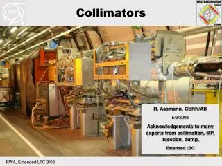
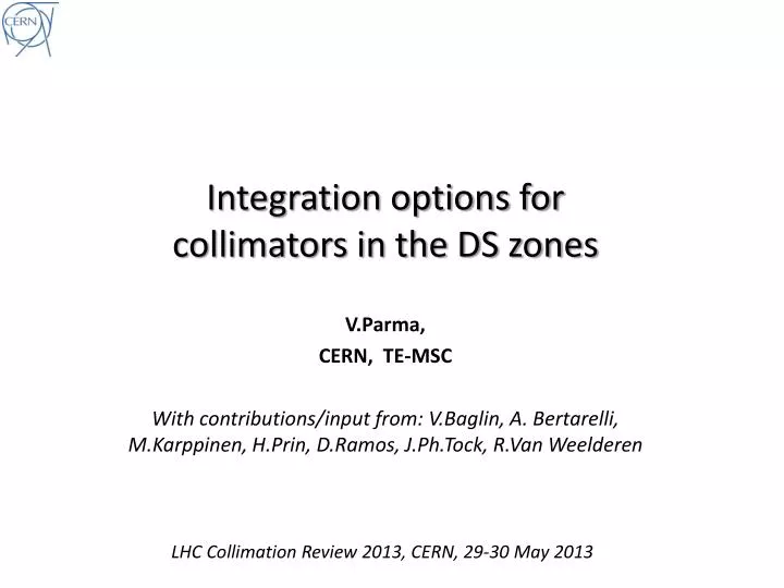
Integration options for collimators in the DS zones. V.Parma, CERN, TE-MSC With contributions/input from: V.Baglin, A. Bertarelli, M.Karppinen, H.Prin , D.Ramos , J.Ph.Tock, R.Van Weelderen. LHC Collimation Review 2013, CERN, 29-30 May 2013. Content.

E N D
Integration options for collimators in the DS zones V.Parma, CERN, TE-MSC With contributions/input from: V.Baglin, A. Bertarelli, M.Karppinen, H.Prin, D.Ramos, J.Ph.Tock, R.Van Weelderen LHC Collimation Review 2013, CERN, 29-30 May 2013
Content • The LTC (TCLD collimators in warm sections of the DS) • LTC integration issues in Pts.1,2,3,5 and 7 • Options for an 11T+collimator assembly • Warm collimator option • Why not a cold collimator? • Timeline • Summary
Content • The LTC (TCLD collimators in warm sections of the DS) • LTC integration issues in Pts.1,2,3,5 and 7 • Options for an 11T+collimator assembly • Warm collimator option • Why not a cold collimator? • Timeline • Summary
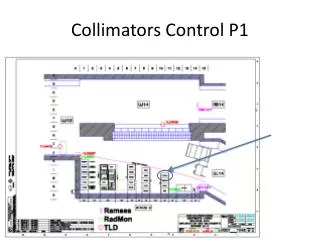
Warm collimators in the DS: the LTC option studied for Pt.3 IP3 R33 RZ33 R34 11L3 10L3 9L3 8L3 7L3 QRL Q10 Q7 Q11 Q9 Q8 DQS Conn.cryostat DFBA TCLA BTVM 4’500 mm 4’500 mm 46 mm QRL Q10 Q7 Q11 Q9 Q8 DQS DFBA TCLA BTVM New Collimatorassembly (LTC) New Collimatorassembly (LTC) Short Conn.cryostat • wasaimedatShut-Down 2012-2013 (was no time for 11 T magnets!) • move 24 existingmagnets and DFBAs (consideredcritical but feasible) • Option studiedmaking use of existing design solutions (for time reasons)
DS Collimator Assembly (LTC) Q8 MB LTC (Y.Muttoni, EN-MEF) Collimator Module (TCLD) • W jaw length 1 m • overall length 4.5 m Cryostat (“by-pass”) (QTC) See A.Bertarelli’s presentation 1 prototype cryostat constructed
Cost Estimate (P+M) Up to date, M expenditures: • < 3 MCHF (estimate) • Includes design studies (also committed) • Components/materials ordered (end caps, supports, raw material…) LHC Collimation Review 2011, CERN 14-15 June 2011 FTE.y kCHF • Key figures: • 21.5 MCHF • 50 FTE.y LHC Collimation Review 2011, CERN 14-15 June 2011
Summary of main implications • Disconnect and remove: • 16 dipoles, 8 SSS, 2 Connection Cryostats, 2 DFBA • Displace by 4.5 m: • TCLA, DQS, BTVM (depending on point. In 3L) • Heavy cable re-layout work: • ~600 cables to be shortened, ~800 cables to be extended (warm and cooled cables) • Re-routing (through new cable duct UP33/R34); connections • Civil engineering: • Remove, displace and fix jacks to ground • Grind passage wall (3-5 cm) on 2x100m length • Drilling new cable duct UP33/R34 • Modification of jumpers of Q7, Q9 and DFBAs (on surface or in the tunnel) • Shortening of DSLC (cryostat+superc.cables) in 3R • Design and produce new equipment: • 4 (+1) DS collimator assemblies (LTC) • 2 (+1) Short Connection Cryostats (SCC) • 2 QRL extensions • Re-install and interconnect DFBA, magnets, SCC, LTC
DS Collimator Assembly (LTC): reviews Reviews: • QTC design & integration in May 2011 (http://indico.cern.ch/conferenceDisplay.py?confId=139092) • LHC collimation review in June 2011 (https://indico.cern.ch/conferenceDisplay.py?confId=139719 ) Recommendations and decisions: • LTC option considered feasible but complex and heavy(i.e. incompatible with LS1) Recommended to delay to LS2: still to be decided • Pursue design and prototyping of the QTC: done (See A.Bertarelli’s talk) • Postpone decisions while endorsing the pursue of alternative scenarios with stronger dipoles magnets (11 T magnets): in progress (see slides ahead)
Status of QTC and SCC • QTC prototype constructed, awaiting validation cold testing (planned Sept. ‘13) • Preliminary design of Short Connection Cryostats done in 2011-12 (now stopped). In case of LTC for LS2, detailed engineering/production to be done • Remains a viable but heavy solution if needed (probably OK for 1 point at most) Short Connection Cryostat QTC prototype
Content • The LTC (TCLD collimators in warm sections of the DS) • LTC integration issues in Pts.1,2,3,5 and 7 • Options for an 11T+collimator assembly • Warm collimator option • Why not a cold collimator? • Timeline • Summary
Dispersion suppressor zones P1, after LS1: bus-bars QF and QD stop after Q11 easier integration in QTC. Much easier if done in LS3 (DFB on surface) P3, studied in detail P5, same as P1 P6: No Q7, jumper on Q10 and not Q9 1 QRL extension more, 17th CC @6R, beam dumps,… P7, similar to P3 CERN, 11 October 2011
Dispersion suppressor zones : 1,2,5(and 8) Line N configuration (Line N needs removal/re-installation to displace magnets): * In points 3&7: 600 A cable only = arc configuration (Experience available) * In points 1,2,5,8: 600 A & 6 kA = No experience with removal, no procedure tested CERN, 11 October 2011
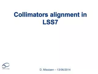
IR specificities For Pts 1,3,5,7 : The DS zones are very similar in terms of layout (but not studied in detail!) IR3 : Checked and validated ; See drawings LHCLJ_3U0035 to 0045 IR2 could necessitate a different collimation optics for only one collimator slot Left of IR2, there is the injection line and the QRL that are constraining differently the available space Differences in design, tooling, procedures, … CERN, 11 October 2011
IR2 specificities DSL2 DFBAs at P2 are also feeding Q6 so if cryomagnets have to be displaced, this would be much heavier than point 3. DSR2
summary on integration issues • No show-stopper identified, but specific integration issues from point to point each point deserves a dedicated study to confirm feasibility IR specificities: • IR 3: Studied in detail • IR 2: • Line N configuration (600A+6kA): complex and no disassembly/re-assembly experience (also true for IR1 and 5) • DFBA also powers Q6: displacement of DFBA heavier. Integration space to be checked. • IR2 Left: injection line & QRL special routing: special space allocation, deserves a dedicated study • for a single collimator slot, what is the optics correction? • IR 1 & 5: • DS layout: similar to 3,7 • Line N configuration (600A+6kA): same as IR 2 • After LS1, QF and QD bus-bars stop after Q11: easier QTC construction/integration • If done at LS3, new DFBs on surface: easier integration of QTC • IR 7: • If QTC during LS2 coupled to displacement of DFB+SC link (R2E): easier integration of QTC
Content • The LTC (TCLD collimators in warm sections of the DS) • LTC integration issues in Pts.1,2,3,5 and 7 • Options for an 11T+collimator assembly • Warm collimator option • Why not a cold collimator? • Timeline • Summary
Dipole integration layout • Remove and replace MB • Preserve standard interconnect (i.e. standard interfaces) • 15’660 mm (IC plane to IC plane) space constraint
The “Collimator in the middle”, preferred option 15’660 (IC to IC plane) ~6’257 (LCM) ~6’257 (LCM) Line X (H.exch.) ~2’400 beam tubes Line M (B.Bar line) 250 250 Note: 2 pairs of standard MCS and MCDO canbeincluded.
5.5m 11T magnet Latest input from M.Karppinen Splice-block Lcoil = 5’415 75 38 End plate 114 6´257 (Ltotal) 5´772* B-Bar Expansion lyra Standard dipole end cap 242.5 B-Bar Fixed point 242.5 * end-plate to end-plate Note: One pair of standard MCS and MCDO canbeincluded in end caps.
Magnet cold mass and beam lines Beam screen termination with compensation for differential displacements: 213 mm if standard; eventually 181 mm if optimised with a short nested bellows Beam screen termination, fixed side: 122 mm RF bellows module for magnet thermal contraction: 165 mm if standard; 147 mm if new design with shorter stroke in proportion to cold mass length “Standard” length scenario; 6’257+213+165+165+122+ 6’257 = 13’179 mm If optimisation proves feasible: 6’257+181+147+147+6’257+122 = 13’111 mm (D.Ramos) Assuming cold bore diameter 50 mm
Collimator length • 1000 mm tungsten active length • 2x100 mm for tapering and pick-ups • 2x140 mm for RF transitions • Total: 1480 mm
Mechanical and vacuum decoupling • RF shielded gate valves • For independence of vacuum operation • Must be staggered: 2x75 mm • Do not exist for low temperature. External actuator with long stem • RF shielded expansion joint modules for: • Installation and removal • Thermal compensation • Independent alignment of the collimator: • Possibly down to 100 mm, if special design (D.Ramos) • Port for RF ball: 100 mm Total length 2x(100+2x75+100) = 700 mm
Warm collimator layout Warm Collimator Module 2’180÷2’380 100 ÷200 100 150 140 1200* PIMs CWT RF ball Vac. Port Vac. Gates Bellows Transition Jaw Transition Bellows Vac. Gates RF ball Vac. Port With input from A.Bertarelli, EN-MME * Jaw length includes 2x100mm end taperings.
Chasing after the mm… • Space remains too tight at this stage of the study (with a 1m collimator jaw) • Optimization of many key items in parallel to make up for the missing space, not just a matter of integration • It is now the right time to start a design effort starting from the existing design (-731mm), followed by an optimization/redesign aimed at reducing length to the 15’660 mm gap: • Existing designs Conceptual design of cryo-assembly by end of 2013 (experienced designer + PE) • Optimization/redesign Detailed design & engineering in 2014 (experienced designer(s) + PE + system engineers)
Sketch of a possible layout 15’660 (IC to IC plane) ~2’380 ~6’214 (LCM) ~6’214 (LCM) MCS MCDO 250 250 ~300* ~142 Splicesdoneatassembly Fixed support Sliding support B-Bar Expansion lyra ~300* ~142 B-Bar Fixed point External jack * Experiencefrom QTC bus-bars routing
Content • The LTC (TCLD collimators in warm sections of the DS) • LTC integration issues in Pts.1,2,3,5 and 7 • Options for an 11T+collimator assembly • Warm collimator option • Why not a cold collimator? • Timeline • Summary
Why considering a cold collimator? • Since it’s cold, no need for cold to warm transitions, hence the overal installation length may be shorter(-330mm)
Preliminary study Cold mass DS collimation pre-study, June 2010 External actuation system D. Duarte Ramos Ch. Mucher
The Cold Collimation Feasibility Study (CCFS) The Cold Collimator Feasibility Study (CCFS) worked on the issue in 2011-12: • Verify the feasibility of installing cold collimators, housed in cryo-assemblies, in the continuous cryostat during LHC’s LS2, as required by collimation in several machine IR’s (pt.1, 2, 3, 5 and 7) Specific goals: • Analyze configurations of cold collimators coupled to 11 T magnets; • Identify potential show stoppers, related to the layout schemes or operational aspects of the technical systems (vacuum, cryogenics, machine protection, alignment, etc). WG composition: Collimators: A.Bertarelli, EN-MME; F.Cerutti, EN-STI; Vacuum : V.Baglin, TE-VSC; Cryogenics : R.Van Weelderen, TE-CRG; 11 T magnets: M.Karppinen, TE-MSC; Machine optics, (R.Assmann, BE-OP); Machine Layout, Cryostat & Integration: V.Parma (J.Ph.Tock),TE-MSC; Collimator project leader (R.Assmann, then replaced by S.Redaelli, BE-OP); HL LHC project leader (L.Rossi, TE) Meetings: • Chaired by V.Parma (alternate J.Ph.Tock); Scientific secretary (all, at turns) • Minutes and workspace: https://espace.cern.ch/CCFS/default.aspx Reporting: • Collimation Upgrade Management Meeting: • February 2012, status reported by V.Parma • January 2013, status reported by D.Ramos
Main findings • Cold collimator version brings limited advantage in longitudinal compactness (-330 mm of CWT) as compared to a warm version • …while adding technological complexity and challenges: • Risk on machine availability: moving parts into the LHC continuous cryostat machine warm-up for interventions • Integration of beam vacuum functionalities: • Minimise gas reservori: bakeout as a must; i.e. cold gate valves • Control of vacuum dynamics: beam screens, perforated BS for H2 pumping to cold bore • T collimator > 90 K (avoid CO2 instabilities), and < 150 K (avoid H2O instabilities) • Development R&D (i.e. cost/human resources/time) essentially in : • Beam vacuum dynamics • Cold gate valves (not available on the market) • Collimator mechanics • Vacuum chamber and cooling • Support and alignment • New concept: jaw at > 90 K requires cryogenics cooling circuitry • New designs:validation requires lots of testing • Engineering resources: heavy needs Considering the marginal advantage and it is recommended not to pursue any further effort on a cold collimator version
Content • The LTC (TCLD collimators in warm sections of the DS) • LTC integration issues in Pts.1,2,3,5 and 7 • Options for an 11T+collimator assembly • Warm collimator option • Why not a cold collimator? • Timeline • Summary
Timeline for LS2 11 T + collimators assy ready for installation 1st 11T proto 2-in-1 (c.f.r. M.Karrpinen’s talk) 11 T + collimators assy testing 11 T + collimators cryostat assembly Cryostat procurement 11 T + collimators cryostat Engineering & Design Latest start of Engineering & Detailed design To be elaborated based on collimation needs (i.e. no. of assemblies needed)
Summary • The LTC option is viable but remains a heavy option; is at present the only one which satisfies machine integration in the DS. • The LTC option was studied in detail for IR3; it remains possible for other points of interest (no showstopper so far) but considering the complexity and specificity of each point it should be studied in detail. • The “11T+collimator” option(with a 1 m W jaw) still does not fit in a standard dipole gap. Should now move to a conceptual and detailed design phase. • The “11T+collimator” option can be successful only if several items are re-designed/optimized in parallel (i.e. all actors concerned have to play the same game!). • In order to be ready for LS2, there is a heavy design work ahead (which should start now) which should be supported by construction of prototypes and/or mock-ups and a qualification program before the machine units are constructed. • The “cold collimator” option is not considered a viable and interesting one.
Answers to specific questions from S.Redaelli for the review • Recent developments and final design choice: “warm” vs “cold” design: Answer: Yes: “warm” • Integration issues and feasibility in the different IRs: IR1/2/5/3/7 Answer:Yes, but IR dependent: dedicated studies needed to rule out possible show-stoppers • Can/should we still keep open to option of moving magnets around in DS’s? Answer:Yes • Review issues for different IR: Is it worth in all cases betting on the 11T dipoles? Answer: This is the most convenient solution. Adequate resources allocation should be ensured depending on the extent of the collimation needs
Differences are coming from the DFBA type and the elements on the IR side. P3 for reference: P1 (5):
Differences are coming from the DFBA type and the elements on the IR side. P2 (Very different): DFBAs at P2 are also feeding Q6 so if cryomagnets have to be displaced, this would be heavier
Differences are coming from the DFBA type and the elements on the IR side.
Differences are coming from the DFBA type and the elements on the IR side.
Differences are coming from the DFBA type and the elements on the IR side.