Download
1 / 21
210 likes | 343 Views
Nonlinear Applications for Automotive Engine Control. By: Sajid Islam. An Introduction. This presentation will discusses nonlinear automotive engine control methods. Our objective is to use nonlinear control methods which will yield an easier and pleasing shift for the user.

E N D
Nonlinear Applications for Automotive Engine Control By: Sajid Islam
An Introduction • This presentation will discusses nonlinear automotive engine control methods. • Our objective is to use nonlinear control methods which will yield an easier and pleasing shift for the user. • Methods discussed include sliding method control, speed-control approach, and relationships between speeds and desired torque trajectories
An Introduction-Problem • During a typical automotive transmission upshift, there is a large decrease in the transmissions output torque. This can be the result of the torque being transferred from high to low gear. • Modulating engine torque can smooth these output transients well. The methods of sliding mode and speed control will allow smoother gear shifts. • Overall, the user will enjoy improved performance of their vehicle.
Denoting Variables • we -Engine Speed • wt -Torque Converter Turbine Speed • wcr -Transmission Reaction Carrier Speed • ww-Wheel Speed • R’s-Represent first, second, and differential gear ratios
Transmission Clutch and Output Torque 1st clutch
Engine Torque Model • This can be used as a simulation model to assess controller designs or system responses • These particular models vary depending on which inputs are available to the model.
Engine Torque Model Block Throttle Intake Manifold Digital Exhaust Gas Recirculation Torque Production Fuel Injection Idle Air Control
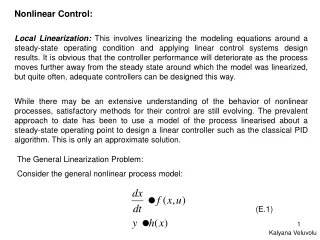
Speed-Error/Sliding Control Formulation • In the sliding-mode nonlinear control formulation, the control engineer defines an error. • This error (e) is defined by the difference between a measured time-domain trajectory and the desired trajectory. e= xn-xnd • Our nonlinear state-space equations dx/dt= f(x, t) + g(x, t) – The notation f(x,t) is a function f of parameters x and t which represents engine speed.
Boundary Layers • A boundary layer of thickness is establised around the sliding surface in order to relieve any chatter that results from implementation of this controller. • The upcoming figure will show how chatter can be reduced or completely eliminated by using the boundary layers. • Sliding surface and sliding mode equation: S= Tbr-Tbrd *Difference of Engine brake torque and Desired Engine Brake Torque
Model Difficulties • Our problem in this situation is that although the model predicts the mean torque, one needs to be cautious when calculating time derivatives of the model. • There have been cases of extremely large errors because of inappropriate usage of the predictive model
Model Difficulties • Also relatively high costs and low reliability of most torques sensors are not a cost-effective strategy • Overall these problems drive the need to develop more speed control algorithms that will be more easier and efficient to use.
Sliding-Mode Engine Control Algorithms • This method can be used to modulate engine speed and turbine speed. This can result in improved responses. • Throttle angle and spark advance will be two control parameters. Also the carrier speed will be controlled by modulating clutch pressures. • Therefore, to control engine speed (we), the sliding surface can be defined in engine speed-error formula discussed before.
Continued • In this situation we can differentiate with respect to time which will give us the sliding-mode equation. Ti is the engine indicated torque, Tf/p denotes engine friction and pump torque, Tp is torque converter and Je is the engine and pump polar inertia. • In this equation, an engineer can substitute torque converter model to estimate pump torque.
Continued • Overall, these gains can estimate desired engine response, because they represent how much relative control effort will be given to bring the error to zero. • The control engineer should also be cautious when setting the spark influence. Usually setting a high spark yields more engine response, but can also cause mechanical problems.
Nonlinear Considerations • Since turbine speed is very difficult to control because of its fluid coupling of the torque converter, the engineer needs to consider its unpredictable behavior. • In this case, output torque of the torque converter can be modeled as a nonlinear function of the pump(engine) and turbine speeds. • Torque or acceleration is also a nonlinear function that should be considered.
Conclusions • Overall, our purpose here is to discuss how sliding mode nonlinear control design can be used to enhance shift quality through engine control. • Our findings are that the engine speed can be controlled very well using the sliding-mode controller. The errors are usually close to zero. Also the turbine speed requires large control actions to stay up with desired trajectories.
Conclusions & Advantages • To improve turbine speed response from engine control we can increase the damping of the torque converter. • The advantages of increased response must be considered along with the disadvantages that engine torque or acceleration will be transmitted to the drive train through the locked torque converter. The speed control approach to sliding mode engine control can relieve many of these implementation problems that have to do with torque control.
Acknowledgements & Credit • This specific research was sponsored from Power Systems Research Department of General Motors Research Laboratories. • There is also an early version of this research which took place at 1989 American Control Conference, Pittsburg, Pennsylvania. • J.H Park (M.I.T.) who worked closely to develop the transmission speed-control algorithms that complement the engine controls.
Reasons for Topic • Practicality of nonlinear situations in a traditional engineering field. • Enhancing knowledge of automotive framework, components, and design. • Curious to see how performance is maximized for an automobile. And also how the user can enjoy their driving experience.