Download
1 / 19
190 likes | 349 Views
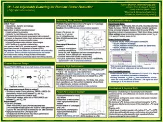
On-Line Adjustable Buffering for Runtime Power Reduction. Andrew B. Kahng Ψ Sherief Reda † Puneet Sharma Ψ Ψ University of California, San Diego † Brown University. Outline. Introduction Adjustable Buffering Methodology Experiments & Results Conclusions. Power: First-Class Objective.

E N D
On-Line Adjustable Buffering for Runtime Power Reduction Andrew B. KahngΨ Sherief Reda† Puneet SharmaΨ ΨUniversity of California, San Diego †Brown University
Outline • Introduction • Adjustable Buffering Methodology • Experiments & Results • Conclusions
Power: First-Class Objective • Power bottleneck to Moore’s law • Power-frequency tradeoff exists in CMOS circuits • Much higher power required to operate at high frequency • Techniques to exploit power-frequency tradeoff are of interest • Allow high freq. operation • Can give significant power reduction when max. performance not required • Mainstream approach: Dynamic voltage and frequency scaling (DVFS) Power-frequency tradeoff with VDD scaling
Ideal frequency-power from VDD scaling Actual frequency-power from DVFS Dynamic VDD & Freq. Scaling • Scale down VDD and freq. when high performance not needed • Limitations of DVFS • VDD cannot be scaled down indefinitely • Range of VDD scaling is small and diminishing • Extremely high power at high VDD reduce max. VDD • High Vth to reduce leakage, noise margins, variability, soft errors increase min. VDD • Discrete allowed voltages • Our objective: enable additional modes to exploit frequency-power tradeoff • Useable when VDD cannot be scaled further • Useable without DVFS
Select Transform 32X 16X / 32X Proposal: Adjustable Buffering • Our approach, like DVFS, provides runtime-selectable low-power modes supplement or replace DVFS • Key idea: Lot of logic added for performance, not functionality Turn this logic off when high-performance not needed • Poor interconnect scaling large number of repeaters • 20-30% of cells are repeaters • Fat repeaters are used to improve delay but consume a lot of power • We modify repeaters to dynamically adjust their driving capacity
Outline • Introduction • Adjustable Buffering Methodology • Experiments & Results • Conclusions
Traditional Inverter (INVX8) Adjustable Inverter Adjustable Repeater Design We add PMOS-NMOS pair to turn half the devices off dynamically Control Gate Control Gate “LPM” = ON only half devices operational (low-power mode). “LPM” = OFF all devices operational (high-performance mode). • What power components are likely to reduce in low-power mode? • Short-circuit power: during switching, PMOS & NMOS ON momentarily short circuit between VDD and VSS • High when transition time (slew) is large • Subthreshold leakage: when one of PMOS-NMOS pair between VDD and VSSON
Adjustable Repeater Requirements • Low area overhead • Added PMOS-NMOS pair (LPM devices) takes area • LPM signal to be routed or locally generated • Layout of the new cell must be simple and low area overhead • High performance in high-performance mode • On-resistance of LPM devices may reduce performance • Good power reduction in low-power mode
Control Gate Control Gate Area Overhead • Problem: High performance needed when LPM signal OFF use large control gates large area overhead Delay overhead: increase in delay of adjustable repeater over traditional repeater Solution:Share control gates among multiple repeaters
V’DD V’SS LPM devices shared by two inverters Control Gate Sharing Fewer control gates but virtual VDD (V’DD) and VSS (V’SS) need routing • How many control gates needed? • Compute simultaneous switching rate (SSR) by finding the max. #repeaters that have overlapping timing windows. Time = O(RlogR) (R = #repeaters) • Find total width of all repeater devices controlled by CGs (=WR) • For good performance, width of control gates = 4 x SSR x WR Typical SSR=~10% small area overhead
Ensuring High Performance • Problem: Adjustable repeaters ~5% slower when LPM signal OFF Up to ~5% reduction in circuit performance • Solution:do not use adjustable repeaters on timing-critical paths • Additional constraint: slew constraints not violated when LPM signal is OFF or ON. • We characterize adjustable repeaters (i.e., find delay, slew, power, input capacitance) and then substitute traditional repeaters with adjustable repeaters subject to delay and slew constraints. No loss in circuit performance & no slew violations
Power Reduction in Low-Power Mode Short-circuit energy and leakage reduce OFF OFF Traditional Inverter Adjustable Inverter Reduction in short-circuit energy and leakage for INVX8
Outline • Introduction • Adjustable Buffering Methodology • Experiments & Results • Conclusions
Experimental Validation • Circuits: s38417 (8,890 cells), AES (15,272), OpenRisc (46,732) • Tools: Synopsys HSPICE (SPICE), Design Compiler (synthesis, timing and power analysis); Cadence SoC Encounter (P&R), SignalStorm (library characterization); Artisan TSMC 90nm library models • Other settings: power and timing analysis at slow corner, VDD of 1.1V and 0.9V, activity factor of 0.01.
Results: Power Reduction • We perform comparative analysis of: • Circuit with DVFS • Circuit with DVFS + LPM VDD=0.9 LPM=0 VDD=1.1 LPM=0 VDD=0.9 LPM=1 VDD=1.1 LPM=1 • Both dynamic and leakage power reduce • 6-12% reduction in total power at low-power mode
Routing overhead • LPM, LPM routed to control gates • routing overhead depends on locations of control gates • # control gates small overhead small • V’DD, V’SS routed to all repeaters • For overhead estimation, nets assumed to be Steiner trees Results: Area Overhead • Logic area overhead due to control gates • Depends on SSR • Smaller if control gates can be placed in whitespace
Outline • Introduction • Adjustable Buffering Methodology • Experiments & Results • Conclusions
Conclusions • Presented a novel technique that dynamically trades off power and performance by turning off devices not needed at less than max. performance • Both leakage and dynamic power reduce; total power reduction is 6-12% on our testcases • By sharing of control gates, area overhead reduced to <5.57% • No adverse affect on performance of the circuit when LPM signal OFF • Future work: • Actual layout of adjustable repeaters with routing of V’DD, V’SS, LPM nets to accurately estimate power, performance, area impacts • Customization of more cells especially clock repeaters to further improve power-performance tradeoff
Thank You • Questions?