Download
1 / 45
460 likes | 660 Views
Agenda – Day 1. 8:00 am – 8:15 am Introductions and House Keeping 8:15 am – 8:45 am Session 1: Load Rating Basics 8 :45 am – 9:30 am Session 2: Basic Load Rating Calculations 9:30 am – 9:45 am Break 9:45 am – 11:45 am Session 3: Example – Load Rating Concrete Slab Bridge

E N D
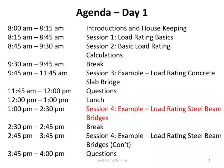
Agenda – Day 1 8:00 am – 8:15 am Introductions and House Keeping 8:15 am – 8:45 am Session 1: Load Rating Basics 8:45 am – 9:30 am Session 2: Basic Load Rating Calculations 9:30 am – 9:45 am Break 9:45 am – 11:45 am Session 3: Example – Load Rating Concrete Slab Bridge 11:45 am – 12:00 pm Questions 12:00 pm – 1:00 pm Lunch 1:00 pm – 2:30 pm Session 4: Example – Load Rating Steel Beam Bridges 2:30 pm – 2:45 pm Break 2:45 pm – 3:45 pm Session 4: Example – Load Rating Steel Beam Bridges (Con’t) 3:45 pm – 4:00 pm Questions Load Rating Seminar
Example – Simple Span Non-Composite Steel Beam Bridge Steps to Follow to Load Rate Bridge Get Geometry of Bridge Calculate Capacity of Beams Calculate Dead Loads Calculate Live Loads Calculate Rating Factors
Example – Simple Span Non-Composite Steel Beam Bridge Step 1 Determine Bridge Geometry
Bridge Geometry • Need the following information: • Deck Cross Section • Deck thickness and build up • Type of guardrail / barrier • F/F guardrail / barrier dimension • Beam size and spacing • Cross frame size and spacing • Span length
Example – Simple Span Non-Composite Steel Beam Bridge Step 2 Calculate Capacity of Beam
Determine Capacity of Beam • Calculating the Capacity (C) for Simple Span Non-Composite Steel Beam • Need the following Steel Beam information: • Yield Stress of Steel Fy • Section properties of the beam
The following equations are for calculating the bending moment capacity of a single-span steel beam or girder with a non-composite concrete deck AASHTO Standard Specifications For Highway Bridges 17th Edition
Compact or Noncompact Section? What is a “compact” section? A compact section in positive flexure satisfies specific steel grade, web slenderness and ductility requirements and is capable of developing a capacity exceeding the moment at first yield, but not to exceed the plastic moment.
Compact section in more basic terms: • Compact sections are permitted to achieve higher stresses because they have: • Compression flanges that satisfy specified width-thickness ratio limits. • Webs that satisfy specified depth-thickness ratio limits. • Compact sections have a high resistance to local buckling. • Note that the following compactness equations are dependent upon both the dimensions of the section and the steel yield strength.
Compact sections must satisfy Article 10.48.1.1 Compression flange width-thickness ratio b = flange width (in.) t = flange thickness (in.) Fy = specified yield point of the steel (psi)
Compact sections must satisfy Article 10.48.1.1 Web depth-thickness ratio D = clear distance between the flanges (in.) tw = web thickness (in.)
Sections meeting Article 10.48.1.1 qualify as compact and the bending capacity is computed as Z = plastic section modulus (in3) AISC Manual of Steel Construction has Z listed for W and S shaped beams. AASHTO 17th Edition, Appendix D, shows the method of computing Z
Calculating the plastic section modulus (Z) The plastic section modulus is the statical first moment of one half-area of the cross section about an axis through the centroid of the other half-area.
Assume built in 1920 Fy = 30,000 psi Section Number B12 12x6 ½ 25 lb/ft Example calculation
Calculate Z * * * = Ignore
Calculate capacity: Mu = Capacity of Beam (C) = 86.15 ft. k.
Sections not meeting Article 10.48.1.1 are noncompact and the bending capacity is computed as Sxt= section modulus with respect to tension flange (in3) For a single-span, non-composite steel beam or girder, Sxt= S • Values of S for rolled sections are listed in the AISC Manual of Steel Construction and for older beams in Appendix B. • The compression flange of a single-span beam or girder is considered fully braced by the concrete slab, with or without shear studs, provided that the deck is in contact with the beam or girder.
Mu as computed using equations (10-92) or (10-98), whichever applies, is the capacity (C) in the equation
Sample Calculation for Capacity of Beam Beam = W30 x 132 Bridge Built in 1975 and has an Fy = 36,000 psi From AISC Manual for W30 x 132: bf = 10.545 in. tf = 1.0 in. D = 26.75 in. tw = 0.615 in. Z = 437 in 3 (Plastic Section Modulus) S = 380 in 3 (Elastic Section Modulus) FYI: 437 / 380 = 1.15
Sample Calculation for Capacity of Beam Check for Compact Section: 1. bf / tf < 4110 / Fy ½ 10.545 / 1.0 < 4110 / 36,000 ½ 10.545 < 21.66 Satisfies 2. D / tw < 19230 / Fy ½ 26.75 / 0.615 < 19230 / 36000 ½ 43.50 < 101.35 Satisfies Beam is Compact therefore: Mu = Fy x Z Mu = 36 ksi x 437 in 3 x 1/12 = 1311 ft. k Beam Capacity (C) = 1311 ft. k
Example – Simple Span Non-Composite Steel Beam Bridge Step 3 Calculate Dead Loads
Example – Simple Span Non-Composite Steel Beam Bridge Step 4 Calculate Live Loads
Calculate Live Load Moments Axle Live Load (LL) Moments: (see Appendix C) L= 50 ft. HS 20 LL Moment = 627.9 ft. k. 2F1 LL Moment = 7.5L+ 83.33/L – 49.95 = 326.7 ft. k 3F1 LL Moment = 11.5L + 14.696/L – 94 = 481.3 ft. k 4F1 LL Moment = 13.5L + 130.67/L -140 = 537.6 ft. k 5C1 LL Moment = 11.5L + 31.391/L -106 = 469.6 ft. k
Calculate Live Loads Calculate Impact factor L= 50 ft. I = 50 / (L + 125) I = 50 / (50 + 125) = 0.29 < 0.30 I = 29 %
Calculate Live Loads Calculate Live Load Distribution Factor (LLDF) LLDF Interior Beam: Number of Lanes on Bridge = 28’ / 12’ = 2.3 = 2 lanes Concrete deck Beam Spacing = 8.0 ft. Therefore from AASHTO Standard Specification for Highway Bridges Table 3.23.1: LLDF = S / 5.5 = 8.0 / 5.5 = 1.45 wheels
Calculate Live Loads Calculate Live Load Distribution Factor (LLDF) LLDF Exterior Beam: LLDF = 8.0/8.0 P + 2.0/8.0 P = 1.25 wheels
Calculate Live Load Moments MLL+I = MLL x ½ x (1+I) x LLDF ½ factor gets moments in terms of wheels Calculate MLL+I for Interior Beams: HS 20 MLL+I: 627.9 x ½ x 1.29 x 1.45 = 587.2 ft. k. 2F1 MLL+I: 326.7 x ½ x 1.29 x 1.45 = 305.5 ft. k. 3F1 MLL+I: 481.3 x ½ x 1.29 x 1.45 = 450.1 ft. k. 4F1 MLL+I: 537.6 x ½ x 1.29 x 1.45 = 502.8 ft. k. 5C1 MLL+I: 469.6 x ½ x 1.29 x 1.45 = 439.2 ft. k.
Calculate Live Load Moments MLL+I = MLL x ½ x (1+I) x LLDF ½ factor gets moments in terms of wheels Calculate MLL+I for Exterior Beams: HS 20 MLL+I: 627.9 x ½ x 1.29 x 1.25 = 506.2 ft. k. 2F1 MLL+I: 326.7 x ½ x 1.29 x 1.25 = 263.4 ft. k. 3F1 MLL+I: 481.3 x ½ x 1.29 x 1.25 = 388.0 ft. k. 4F1 MLL+I: 537.6 x ½ x 1.29 x 1.25 = 433.4 ft. k. 5C1 MLL+I: 469.6 x ½ x 1.29 x 1.25 = 378.6 ft. k.
Example – Simple Span Non-Composite Steel Beam Bridge Step 5 Calculate Rating Factors
Calculate Rating Factors • RF = Capacity – A1 (DL) • A2 (LL + I)
Calculate Rating Factors Capacity = 1311 ft. k (W36 x 132) Dead Load Moment Interior Beam = 337.5 ft. k. Exterior Beam = 337.5 ft. k (not normally same) MLL+I: Interior Beam HS 20 MLL+I = 587.2 ft. k. 2F1 MLL+I = 305.5 ft. k. 3F1 MLL+I = 450.1 ft. k. 4F1 MLL+I = 502.8 ft. k. 5C1 MLL+I = 439.2 ft. k. Exterior Beam HS 20 MLL+I = 506.2 ft. k. 2F1 MLL+I = 263.4 ft. k. 3F1 MLL+I = 388.0 ft. k. 4F1 MLL+I = 433.4 ft. k. 5C1 MLL+I = 378.6 ft. k.
Calculate Rating Factors • RF = Capacity – A1 (DL) • A2 (LL + I) Inventory Rating for Interior Beam – HS Rating RF = 1311 – 1.3 (337.5) = 0.685 2.17 (587.2) HS Load Rating = 0.685 x 20 = HS13.7 (Inventory) Rating in tons = 0.685 x 36 tons = 24.7 tons (Inventory)
Calculate Rating Factors • RF = Capacity – A1 (DL) • A2 (LL + I) Operating Rating for Interior Beam – HS Rating RF = 1311 – 1.3 (337.5) = 1.143 1.3 (587.2) HS Load Rating = 1.143 x 20 = HS22.8 (Operating) Rating in tons = 1.143 x 36 tons = 41.1 tons (Operating)
Calculate Rating Factors • RF = Capacity – A1 (DL) • A2 (LL + I) Operating Rating for Interior Beam – Ohio Legal 4F1 Truck: (largest MLL+I) RF = 1311 – 1.3 (337.5) = 1.334 1.3 (502.8) Percent Legal Load = 1.334 x 100 = 133% say 135 % Rating in tons = 1.334 x 27 tons = 36.0 tons
Calculate Rating Factors • RF = Capacity – A1 (DL) • A2 (LL + I) Operating Rating for Interior Beam – Ohio Legal 2F1 Truck: RF = 2.196 Load Rating = 32.9 tons 3F1 Truck: RF = 1.491 Load Rating = 34.3 tons 5C1 Truck: RF = 1.528 Load Rating = 61.1 tons
Calculate Rating Factors Prepare a Summary Report: Figure 908 in BDM has one example
Congratulations - you have load rated a single span steel beam bridge Questions ? ? ? ? ?