Download
1 / 39
520 likes | 1.65k Views
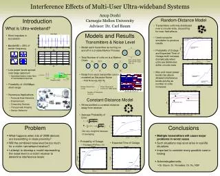
MULTI-FREQUENCY AND ULTRA-WIDEBAND ANTENNA RADOMES. Dr. D .J. Kozakoff Marietta, GA, USA. Radome. A dielectric (RF transparent) cover placed over an antenna in order to protect it from the environment A technology spin off of WWII. Reasons for its Development.

E N D
MULTI-FREQUENCY AND ULTRA-WIDEBAND ANTENNA RADOMES Dr. D .J. Kozakoff Marietta, GA, USA
Radome • A dielectric (RF transparent) cover placed over an antenna in order to protect it from the environment • A technology spin off of WWII
Reasons for its Development • The maximum speed of an aircraft is limited to the speed at which external antennas are able to survive. • In WWII a plastic cover over a B18 bombers radar antenna was the first known application • Today, in what applications are radomes used?
Maritime Applications Ocean Liners Small Craft
Telecon Applications Parabolic Reflector Antennas Hog Horn Antennas
Radar and SATCOM Applications Air Traffic Control SATCOM
As a Structure to Conceal an Enclosed Microwave Communications Antenna Antenna Within Structure External view Concealfab Corp.
As a Structure to Conceal an Enclosed SATCOM Antenna Concealfab Corp.
Revise the last Question • Are there applications where radomes not used? • Not many!!!
Bottlenecks to Consider • Within a radome, the system bandwidth is limited by the radomes bandwidth. • The noise floor (system noise temperature) cannot be less than radome noise temperature (in the order of 10o K for every 0.1 dB loss.) • The radome depolarization limits the dynamic range in a frequency reuse application.
Reciprocity What a Radome does in the transmitting mode, it does exactly the same thing in the receiving mode (For instance, if a radome had 1 dB of transmission signal loss, it would also attenuate the received signal by 1 dB.
Parameters that Impact Broadband Performance • Wall thickness (thin is generally better) • Wall design: number of layers, thickness, • and permittivity of each layer (more layers • is better.) • Shape (flatness is desirable) • Selection of low loss materials (small loss • tangent is required).
Definition of Walls Types ε1 ε2 ε1 ε1 ε2 ε1 ε2 ε1 Monolithic A or B C B-Sandwich: ε1 < A-Sandwich: ε1 > ε2 C-Sandwich: ε1 > ε2
Multifrequency or Ultrabroadband Approaches in Current Use: Thin Wall Radomes
Monolithic Walls • Walls that are any multiple of a half wave must be precluded because these are narrow band. • Any wall that is thin in terms of wavelength is ultrabroadband but: - generally has poor mechanical strength. - has a loss almost entirely due to reflection (loss tangent value is of little importance)
Multifrequency or Ultrabroadband Approaches in Current Use: Computer OptimizedMultilayer Wall Designs
Computer optimization of multi-wall radomes considerations • Iterate all possible layer thicknesses in half ply • (6 mil) increments • Coarse search followed by a fine search and use • of convergence algorithms was important when • computers were slow (4 MHz) • Brute force search through all combinations is • feasible with today’s high speed PC computers • (2 GHz +) • Optimized solutions are not unique, that is various • combinations of wall thicknesses may suffice
Multilayer Computer Optimization Procedure • Describe wall type and max and min thicknesses of each layer • Input layer dielectric constants and loss tangents • Define performance desired in each frequency range • Iterate radome transmission calculations until acceptable performance is achieved.
Multifrequency or Ultrabroadband Approaches in Research or Development
Approach 1: Matched Materials Wave Impedance of a Radome Material Where: = Relative permeability = Relative permittivity
Approach 1: Matched Materials • If the relative permittivity of a radome material is equal to its relative permeability then the intrinsic impedance is the same as the intrinsic impedance of free space and there is no radome reflection loss. • Materials with a relative permeability greater than one do not yet exist above about 1 GHz (above 1 GHz the only practical matched material approach is a radome material both relative permittivity and relative permeability close to 1).
Summary for Matched Materials Approach • Materials development needed to find a material with a relative permeability greater than 1 above 1 GHz. (This could be incorporated with a standard dielectric using dielectric mix formulas in order to achieve a matched material).
Approach 2: Metamaterials • Metamaterials are periodic structures that • Exhibit a negative refractive index • Microwave metamaterials are usually • constructed as arrays of electrically conductive • elements which have suitable reactance • characteristics. • Passive circuits. • (Note: metamaterial core • could replace standard • Honeycomb core in an A • Sandwich radome.)
Metamaterial Radome Features • A dielectric layer and adjacent to a suitable • metamaterialused as a radome. • The structure may be non-reciprocal for • incoming and outgoing waves. • Metamaterial radomes can improved power • Transmission over a broad range of antenna • scan angles.
Metamaterial Radome Features • Metamaterial radomes can enhance out of • band signal rejection. • Commercial metamaterial radomes are not • yet state-of-the-art. • Metamaterials are useful for multi-band • Radomes. • Metamaterials ultra wideband radomes (TBD).
Metamaterial References • Use of conjugate dielectric and metamaterial slabs as • radomes, Microwaves, Antennas & Propagation • IET, ISSN 1751-8725, pp.1751-8725, Feb 2007 • Oraizi, H. and M.Afsahi, Design of Metamaterial • Multilayer Structures as Frequency Selective • Surfaces, Progress in Electromagnetics Research C, • Vol.6, pp.115-126, 2009 • Wu, C., H. Lin and J.Chen, A novel low profile dual • Polarization metamaterial antenna radome design for • 2.6 GHz WiMAX, 3rd International Congress on Advanced • EM Materials and Optics, 2009
Approach 3: Pyramidal inner walls • Bandwidth of 10:1 or greater potential. • Performance demonstrated in lab tests over 0 to 60 deg angle of incidence. • Excellent circular pol. characteristics. • This approach has not yet known to have been used in any commercial application.
Pyramidal inner walls reference Bassett,H. L., D.G.Bodnar, G.K.Huddleston and J.M.Newton, Broadband Radome Techniques, AD0920772, Engineering Experiment Station, Georgia Institute of Technology, Atlanta, GA, 1974
Approach 4: Active Radomes • Reconfigurable frequency pass bands and frequency reject bands. • Lightweight and low loss. • An outgrowth of meta-materials technology.
Summary • Current technology thin wall radomes meet electrical requirements for ultra wideband transmission, but not necessarily meet mechanical requirements. • Current technology computer optimized multi-wall radomes using state of the art materials are realizable but very expensive. • Matched material (Approach 1) requires material development break thru to use above 1 Ghz.
Summary (continued) • Approach 2 (Pyramidal surface matching) has been demonstrated in the lab but not yet been commercialized. • Approach 3 (Meta-materials radomes) are passive and are in current research. • Active radomes (Approach 4) are envisioned as a future development offering enhanced features and capabilities.
Thank you for your time in listening to this presentation. Have a good day. D.J.Kozakoff dr.kozakoff@usdigicomm.com