Download
1 / 1
20 likes | 165 Views
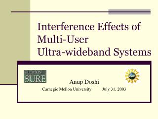
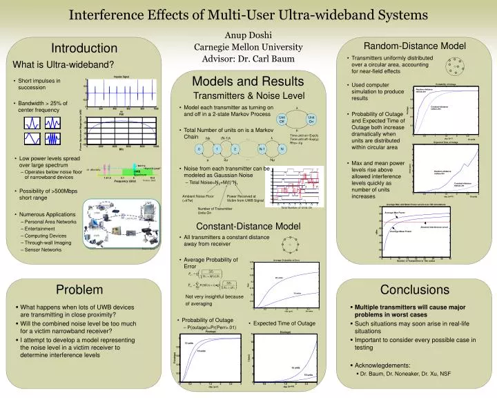
UWB. UWB. (N-1) λ. …. λ. N λ. UWB. 0. 1. 2. N-1. N. LAN/WLAN. …. µ. 2µ. Nµ. UWB. UWB. Broadband. λ. Unit Off. Unit On. µ. 802.11a. PCS. “Part 15 Limit”. -41 dBm/Mhz. UWB Spectrum. GPS. 1.6. 1.9. 3.1. 5. 10.6. Source: Intel. Frequency (Ghz). 2m radius.

E N D
UWB UWB (N-1)λ … λ Nλ UWB 0 1 2 N-1 N LAN/WLAN … µ 2µ Nµ UWB UWB Broadband λ Unit Off Unit On µ 802.11a PCS “Part 15 Limit” -41 dBm/Mhz UWB Spectrum GPS 1.6 1.9 3.1 5 10.6 Source: Intel Frequency (Ghz) 2m radius Introduction Random-Distance Model • Transmitters uniformly distributed over a circular area, accounting for near-field effects What is Ultra-wideband? Interference Effects of Multi-User Ultra-wideband Systems Models and Results • Short impulses in succession • Bandwidth > 25% of center frequency • Used computer simulation to produce results • Probability of Outage and Expected Time of Outage both increase dramatically when units are distributed within circular area • Max and mean power levels rise above allowed interference levels quickly as number of units increases Transmitters & Noise Level • Model each transmitter as turning on and off in a 2-state Markov Process • Total Number of units on is a Markov Chain • Noise from each transmitter can be modeled as Gaussian Noise • Total Noise=N0+M(t)*N1 Time until on~Exp(λ) Time until off~Exp(µ) Rho= λ/µ (µ=1) • Low power levels spread over large spectrum • Operates below noise floor of narrowband devices • Possibility of >500Mbps short range Ambient Noise Floor (=kTw) Power Received at Victim from UWB Signal (µ=10) Total Number of Units On Number of Transmitter Units On Anup Doshi Carnegie Mellon University Advisor: Dr. Carl Baum • Numerous Applications • Personal Area Networks • Entertainment • Computing Devices • Through-wall Imaging • Sensor Networks Constant-Distance Model • All transmitters a constant distance away from receiver Source: Intel • Average Probability of Error Not very insightful because of averaging Problem Conclusions • Multiple transmitters will cause major problems in worst cases • Such situations may soon arise in real-life situations • Important to consider every possible case in testing • Acknowlegdements: • Dr. Baum, Dr. Noneaker, Dr. Xu, NSF • What happens when lots of UWB devices are transmitting in close proximity? • Will the combined noise level be too much for a victim narrowband receiver? • I attempt to develop a model representing the noise level in a victim receiver to determine interference levels (µ=1) • Probability of Outage • P(outage)=Pr(Perr>.01) • Expected Time of Outage (µ=10) (µ=1)