Download
1 / 38
380 likes | 399 Views
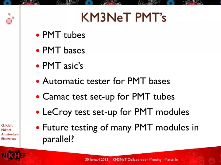
KM3NeT PMT’s. PMT tubes PMT bases PMT asic’s Automatic tester for PMT bases Camac test set-up for PMT tubes LeCroy test set-up for PMT modules Future testing of many PMT modules in parallel?. PMT tubes. Currently PMT tubes from 3 manufacturers: ETEL, Hamamatsu and HZC-Photonics

E N D
KM3NeT PMT’s • PMT tubes • PMT bases • PMT asic’s • Automatic tester for PMT bases • Camac test set-up for PMT tubes • LeCroy test set-up for PMT modules • Future testing of many PMT modules in parallel? KM3NeT Collaboration Meeting - Marseille
PMT tubes • Currently PMT tubes from 3 manufacturers:ETEL, Hamamatsu and HZC-Photonics • Different PMT types per manufacturer • Different pinning diameter and layout of the pins • Different High Voltage division between pins • In principle one PMT base design sufficient for all PMT types • Only minor schematics adjustments to adjust for HV division • But different PCB layout due to different pin layout • Base PCB layout is very critical due to minimal space and HV • Each PMT type needs an unique PMT base !!! KM3NeT Collaboration Meeting - Marseille
ETEL Hamamatsu KM3NeT Collaboration Meeting - Marseille
Hamamatsu PMT’s for PPM-DU • One DOM of PPM-DU uses Hamamatsu PMT R12199-02 • Hamamatsu PMT R12199-02 is probably not the final type • No special PMT base PMT R12199-02 will be produced • 33 ETEL bases are modified for Hamamatsu R12199-02 KM3NeT Collaboration Meeting - Marseille
Hamamatsu PMT for KM3NeT Phase 1 • Current pin layout is a problem for PCB layout of the base • Hamamatsu is requested to change the pin layout • Start PCB layout of unique Hamamatsu base is pending KM3NeT Collaboration Meeting - Marseille
PMT PCB layout very critical due to minimal space and HV KM3NeT Collaboration Meeting - Marseille
Block diagram of PMT PROMiS CoCo KM3NeT Collaboration Meeting - Marseille
Specifications of High Voltage circuit HV circuit, for 10 dynodes PMT • Low ripple • 706 mV1056 8.5 < T(°C) < 22.1 • 0.07% 8.5 < T(°C) < 22.1 • Voltage stabilization 0.95% on 38% input variationVripple < 150 mV/dynode • Low power • Vinput 3.3V • .6 - 1.4 mA3v3at 700 - 1500 V < 4.5 mW(commercial available 50 mW) • Low RFI • dV/dt < 75 mV/µs, RFI -20 dB @ 150 kHz-10 MHz • Adjustable HV • cathode voltage -700 till -1500 V • Small foot print • PCB = 38 - 42 mm Ø • Amplifier charge input:160 fC (corresponds with 1 pe and PMT gain of 1x10^6) KM3NeT Collaboration Meeting - Marseille
ETEL PMT D783FLA base with PROMiS_v2 and CoCo_v2 CoCo PROMiS KM3NeT Collaboration Meeting - Marseille
PROMiS_v2 and CoCo_v2 asic’s KM3NeT Collaboration Meeting - Marseille
Block diagram of CoCo_v2 KM3NeT Collaboration Meeting - Marseille
Specifications of CoCo_v2 KM3NeT Collaboration Meeting - Marseille
Block diagram of PROMiS_v2 KM3NeT Collaboration Meeting - Marseille
Specifications of the PROMiS_v2 A front end ASIC for the readout of the PMT in the KM3NeT detector – D. Gajanana et. al. http://iopscience.iop.org/1748-0221/5/12/C12040/ KM3NeT Collaboration Meeting - Marseille
Preliminary costs estimation ofPROMiS_v2 and CoCo_v2 PROMiS_v2 Quantity Total costs Unit Price MPW run 210 € 8,200 € 39.05 Engineering run 50,000 € 95,000 € 1.90 Low volume run 350,000 € 110,000 € 0.32 Total 400,210 € 213,200 € 0.54 CoCo_v2 Quantity Total costs Unit Price MPW run 210 € 8,200 € 39.05 Engineering run 50,000 € 145,000 € 2.90 € 50,000 for test handler! Low volume run 350,000 € 115,000 € 0.33 Total 400,210 € 268,200 € 0.67 KM3NeT Collaboration Meeting - Marseille
Automatic tester for PMT bases • Depending on final size of KM3NeT up to around400,000 PMT bases have to be produced and tested • For this big volume production the bases have to be tested during production by the assembling company(ies) • Automatic test set-up is being designed suitable to be placed at and operated by assembling company • Test program in LabView will indicate a pass or fail when the base is tested. • In case of a fail, the program will pinpoint to the area on the base causing the failure • Removable mechanical adapters for different type of PMT bases KM3NeT Collaboration Meeting - Marseille
Mechanical overview of tester HV measurementunit(Mezzanine) PMT baseto be tested PMT Baseadapter setwith contactpins FPGA boardwith USBinterfaceto PC Mother board KM3NeT Collaboration Meeting - Marseille
Principle of mechanical PMT base adapter KM3NeT Collaboration Meeting - Marseille
Motherboard with mezzanine and adapter connectors KM3NeT Collaboration Meeting - Marseille
PCB layout of HV measurement units KM3NeT Collaboration Meeting - Marseille
HV barrier Safety system PMT base adapter HV measurement unit 1 supply PMT base PMT Tail Adapter Voltage Adjustment and Current measurement HV barrier HV measurement unit 14 supply Digital value PROMIS outputs Test PROMIS outputs CoCo test frequentie and pulswidth CW High Voltage circuit Promis CoCo Digital values frequentie ad pulswidth Electronics for charge inject PROMIS Control Board Promis PROMIS Digital value for charge adjust Test HV Control And I2C Digital value HV control Discharge capacitors from CW high voltage circuit Digital value of inter dynode voltages KM3NeT Collaboration Meeting - Marseille
PMT base tester FPGA board KM3NeT Collaboration Meeting - Marseille
Camac set-up to test PMT tubes KM3NeT Collaboration Meeting - Marseille
Block diagram of Camac test set-up KM3NeT Collaboration Meeting - Marseille
LeCroy test set-up for PMT’s with base Counter LightSource Pulse generator Trigger Pseudo Octopus board Lemo Driver ToT signal USB I2C Control NI Dark Box KM3NeT Collaboration Meeting - Marseille
LeCroymeasurements • Set HV of PMT at value for gain of 5x10^6 • Without light, measure dark count frequency (<2KHz) • Make histogram of dark count ToT • Set pulse oscillator at 100KHz • Set amplitude of pulse oscillator such that frequency on counter is: darkcount + 10KHz. Amount of light from light source is now a single photon • Trigger LeCroy on pulse generator and make histogram of ToT (small peak at 31ns) • Make histogram of time between trigger and rising edge of ToT signal. This gives the TTS KM3NeT Collaboration Meeting - Marseille
Future testing of many PMT’s with base in parallel ? • Depending on the yield only test samples of PMT tubes(PMT tubes are already tested by manufacturer) • Test all PMT bases before soldering on PMT tube • Preferable and if possible have PMT bases produced, tested and soldered on PMT by PMT manufacturer • Test all PMT’s with base before DOM assembly • Because of high volume testing of PMT’s with base must be done in parallel (long time required in dark box to get quiet) • Possibly make use of DOM electronics with electrical interface to test PC (test 31 PMT’s with base in parallel) • Need to find institute to develop test set-up !!! KM3NeT Collaboration Meeting - Marseille
Summary • Every PMT type needs a unique PMT base • PCB layout of PMT base is critical due to space and HV • Layout PMT base(s) for KM3NeT phase 1 still to design • PROMiS and CoCo asic’s are ready for large production • PMT base tester is being developed to enable testing during assembly by company • New test set-up needed to test many PMT’s with base in parallel • Need to find institute to work on development of this test set-up KM3NeT Collaboration Meeting - Marseille
Thank you !!! KM3NeT Collaboration Meeting - Marseille
Questions ? KM3NeT Collaboration Meeting - Marseille
Backup Sheets KM3NeT Collaboration Meeting - Marseille
Specifications of CoCo_v2 Min Typ Max VDDD 3.0 V 3.3 V 3.6 V IDDD 0.2 mA 1 mA 2 mA SW 500 Hz 50 kHz 60 kHz Frequency depends on the capacitor connected to CF (PIN1) SW 200 ns 6.5 us 7.5 us CSNS 80 mV 100 mV 200 mV KM3NeT Collaboration Meeting - Marseille
CoCo – Cockroft Walton Feedback Control CircuitPin out and chip schematics KM3NeT Collaboration Meeting - Marseille
CoCo_v2 Bonding Diagram KM3NeT Collaboration Meeting - Marseille
Specifications of the PROMiS_v2 • Time resolution : 2ns (Photon arrival time accuracy) • Time-over-Threshold : 1pe → 25ns (1E6 e-)..10pe → 350ns (8000000e-) • LVDS signaling. • Analog Output buffer (see next slide). • I2C slow control. • Comparator threshold adjustment: 0.8V – 2.4V Resolution : 8bits (bin size = 6.25mV) • Reference voltages for High Voltage circuit: 1.9V …2.7V (resolution 8bits)→ High Voltage: -700V …-1500V • Power consumption : ~ 20mW • Technology: 0.35μm CMOS (AustriaMicroSystems) • Immunity to dirty Power supplies • Immunity to voltage breakdowns originated in the PMT KM3NeT Collaboration Meeting - Marseille
LayoutPROMiS_v2 Clk_enable (12) Global_reset (14) Anabuf-(16) Anabuf+(15) VDDD(13) Bondpad name (package pin number) VDDD(13) GNDD(14) GNDD(14) LVDS-(1) SCL(11) LVDS+(2) GNDD(3) SDA(10) 1.25 mm PDIO(9) Vthr(4) VDDA(7) HVDAC(8) GNDA(6) 1.7 mm Preamp(5) Pptrim_busy (open) KM3NeT Collaboration Meeting - Marseille
PROMiS_v2 Bonding Diagram KM3NeT Collaboration Meeting - Marseille
Analog signal output of PROMiS_v2 KM3NeT Collaboration Meeting - Marseille