Download
1 / 20
200 likes | 285 Views
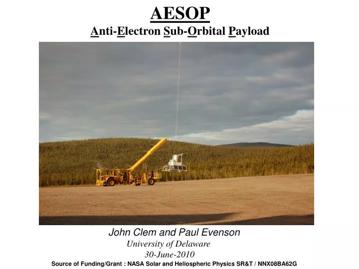
AESOP A nti- E lectron S ub- O rbital P ayload. John Clem and Paul Evenson. University of Delaware 30-June-2010. Source of Funding/Grant : NASA Solar and Heliospheric Physics SR&T / NNX08BA62G. Outline . 1) Objectives 2) Instrument description 3) Flight Observations

E N D
AESOP Anti-Electron Sub-Orbital Payload John Clem and Paul Evenson University of Delaware 30-June-2010 Source of Funding/Grant : NASA Solar and Heliospheric Physics SR&T / NNX08BA62G
Outline 1) Objectives 2) Instrument description 3) Flight Observations 4) Campaign Work area and Flight requirements 5) Current Status and Schedule
AESOP Scientific Objectives To determine the extent to which the large scale structure of the heliospheric magnetic field is important in the propagation of charged cosmic ray particles in the heliosphere. To quantify this effect we intend to measure the time evolution of electron and positron particle fluxes spanning two solar cycles (22 years) 2
To achieve this goal, AESOP was designed to measure the positron abundance in electrons from 200MeV to 5GeV over a full 22 year cycle. (Chickens can fly) AESOP detects electrons with plastic scintillators T1, T3 and G (anticoincidence) and the gas Cherenkov detector T2. The instrument measures the electron energy in scintillator (T4) mounted below a 1cm lead disk and a leadglass (T5) calorimeter. Scintillator T6 also assists in particle identification and energy determination by counting the number of particles that escape the calorimeter. A permanent magnet hodoscope system determines the charge sign and momentum of the electron event. 25
Electrons Positrons AESOP 2006 Flight Vertical axis: Energy measured in the Pb-Glass (T5) calorimeter Horizontal: Deflection in the magnet in units of inverse rigidity. Curve represents the ideal instrument response for positrons (positive side) and electrons (negative side). Red symbols are events tagged as high energy protons Particle ID and energy of each event are assigned using a likelihood analysis
The AESOP summary of positron abundance measurements as a function of energy for different epochs of solar magnetic polarity Solid line is the local interstellar space abundance as calculated by Protheroe (1982). Dashed lines are from Clem et al. (1996) for A+ (top line) and A-. Solid symbols show data taken in the A+ state, while the open symbols represent data taken in the A- state. As expected the observed positron abundances during the 2000s (A-) are clearly lower than that measured during the 1990s(A+). These data are consistent qualitatively with charge sign models, however we are in throes developing a new 3D model that incorporates Heliospheric curvature and gradient drifts
Consider only data at ~1.2GV….. The world summary of the same plot on prior slide 29
Time dependence of positron abundance Black line is a Positron abundance prediction based on the analysis of Clem et al. (1996). 2011 Flight 2009 Flight Blue line is a very preliminary model based on cosmic ray drifts near the current sheet and drifts over the Solar poles. Vertical was scaled to fit the data.
Time dependence of positron abundance (black) and anti-proton ratio (red) at a rigidity of roughly 1.3GV. Black line is a Positron abundance prediction based on the analysis of Clem et al. (1996). Same on previous slide. Red line is an antiproton/proton ratio model Bieber et al. (1999). Dashed lines are the predicted results for future observations. Anti-protons were measured by the series of BESS flights 2011 Flight 2009 Flight
AESOP flight requirements MinFloat Altitude: 100kft MinFloat Duration: 60hrs Desired Float Altitude: 130kft Desired Float Duration: 40hrs (Altitude excursions are very helpful) Flight Path should remain North of the 0.5GV geomagnetic cutoff
Altitude is a Priority 1990s Prior Flight 2000s Estimated positron background (1.2GeV bin) for Solar min A- period as a function of depth
AESOP Instrument Flight Power: Power 100watts Plan to re-fly Charge Controller originally from PSL. SunCattype Solar Panels Flight Gas: 265cft bottle of Neon (Metric thread adapter and Valve Helmet ) AESOP Telemetry: Downlink: TDRSS high rate, LOS Uplink: TDRSS, Iridium, LOS, 4 Discrete Lines (Instr. Power, Black Box) Reliable Fast Internet Service to OCC (Palestine)
Work Space Requirement for LEE and AESOP 40x40ft work space 2ton overhead lift 5 x 60Hz ,115V power outlets 50amp Phone line Reliable internet service to OCC (Palestine) Office Space
Gas Bottles 3 x Neon 265cft(2400psi) 4 x Nitrogen (Comm Grade) 265cft(2400psi) 2 xHe 265cft(2400psi) 2 xC3F8 (R218)15lbs (vapor pressure) 1 x SF6 15lbs (vapor pressure) Palestine: 4 x Neon 265cft(2400psi) 5 x Nitrogen (Comm Grade) 265cft(2400psi) 3 xHe 265cft(2400psi) 2 xC3F8 (R218)15lbs (vapor pressure) 1 x SF6 15lbs(vapor pressure) Esrange:
Milestones: AESOP Refurbish Spark Chambers Replace Trigger Photomultiplier Tubes Calibrate Flight Detectors Check out full integrated science instrument LEE Ready to be shipped We expect to be in Palestine late January and ready for compatibility hanging mid-late February.
Field Personnel: John Clem – Scientist Paul Evenson – Scientist Chris Elliott – Tech James Roth - Tech Jessica Sun – Engineer Jeff Townsend - Student Preparation Time in Field: Atotal 21 day lead-time is required to prepare both AESOP and LEE for flight. This could be reduce to ~15 days if both payloads could be staged simultaneously .
Integrate New Trigger PMTs PVs arrive Refurbished Chambers Calibrate Flight Detectors and Check out full Flight Instrument Lee Flight Ready LEE Hanging pack Arrive CSBF AESOP Hanging LEE Integration AESOP Flight Ready Integration pack 1st crew arrivals into Esrange AESOP Integration Jul Aug Sep Oct Nov Dec Jan Feb Mar May June
We are looking forward to another successful balloon campaign !!