Download
1 / 59
590 likes | 728 Views
Dynamic structural analysis of absorbers with spectral-element code ELSE. Yacine Kadi, Roberto Rocca, Wim Weterings - CERN Luca Massidda - CRS4 Workshop on Materials for Collimators and Beam Absorbers CERN - September, 3-5 2007. Table of Contents. Overview of the Spectral Element Method

E N D
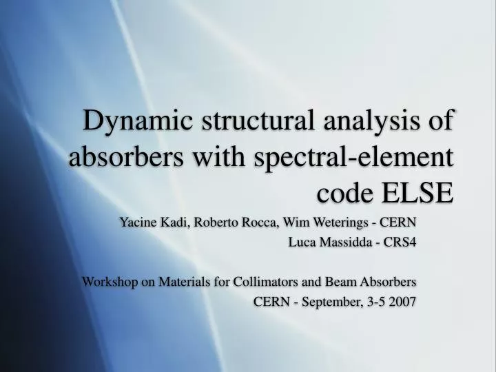
Dynamic structural analysis of absorbers with spectral-element code ELSE Yacine Kadi, Roberto Rocca, Wim Weterings - CERN Luca Massidda - CRS4 Workshop on Materials for Collimators and Beam Absorbers CERN - September, 3-5 2007
Table of Contents • Overview of the Spectral Element Method • TCDS absorber dynamic stress analysis • TPSG absorber dynamic stress analysis • Some thoughts on materials and numerical simulations
The beam dump problem • Particles are dumped in the solid with internal heat generation, calculated by FLUKA • Temperature increases suddenly giving origin to thermal stresses • Elastic waves are propagated through the structure
SEM overview: problem formulation • To give a short introduction to the methodology let us assume we have to solve the following simple PDE problem over a computational domain Ω with Dirichlet boundary ΓD and Neumann boundary ΓN
Weak form • The PDE problem is turned in its weak form
Numerical approximation • The functional space H1(Ω) is infinite dimensional • Two ideas are adopted • Approximate H1(Ω) with the finite dimensional space Vh(Ω) with dimension N, such that Vh(Ω)⊂H1(Ω) • Choose the test function v among the basis of the space Ψi
Numerical approximation • The variational problem may be rewritten as follows for the finite dimensional space Vh(Ω), and it easily turns to a linear system of equations
SE in a nutshell • The domain is split into quad or hexa • Each element is mapped onto a reference element • LGL nodes are introduced (N=3) • Spectral elements are mapped onto the domain You can think of SEM as an extension of FEM
SE in a nutshell • The computational domain Ω is split in a finite set of smaller elements Ωk and each element is obtained by a 1 to 1 mapping from a reference element Ω • The nodes in Ω are placed in the LGL positions ξP, in 1D the zeros of L’N plus -1 and +1 (LN is the Legendre polynomial of degree N) • Shape functions ψ on Ω are the Lagrange polynomials through the LGL nodes ξP
Numerical integration • Integration is performed element-wise • Integrations are evaluated numerically over the reference element by the Legendre-Gauss-Lobatto (LGL) quadrature formula • The choice of the particular position of the internal nodes assures the spectral accuracy
Run-time high order Numerical dispersion implies insufficient accuracy of the method. Appealing for wave problems, with need of accuracy depending on the frequency of the signal to be propagated FE solution implies remeshing Run with spectral degree 1. Analysis with increased spectral degree set to 2 at run-time.
Reasons for SEM • Geometric flexibility of the Finite Elements • High computational efficiency • Spectral accuracy • Run-time high order
Failure criteria: Stassi • Isotropic materials (graphite, titanium, steel, Inconel) are evaluated with the Stassi criterion • The Stassi criterion is suitable for isotropic brittle materials having different tensile and compressive strength (whereas von Mises is only applicable for ductile materials) • The equivalent Stassi stress is calculated on the base of the Von Mises equivalent stress, the ratio between the compressive and tensile strength and the hydrostatic pressure • It is equivalent to the Von Mises stress when the tensile and compressive strengths are equal • Structural safety is assessed on the base of the ratio between the Stassi equivalent stress and the tensile strenght of the material
Failure criteria: Maximum Stress • For anisotropic materials (carbon composites) the maximum stress criterion is adopted • Each component of the stress tensor is compared with the corresponding material strength, either compressive or tensile • The maximum ratio between stress and strength is used to assess structural resistance
Target Collimator Dump Septum • In the first design the TCDS was 3.0 long and had the following material composition: 1m of graphite, 2m of a carbon composite, 1.5m of graphite again, 1m of aluminum nitride and 0.5m of a titanium alloy • The core had a wedge shape determined by the extreme orbit trajectories and is realized by a set of parallelepiped blocks (80mm high, ∼24mm thick and 25mm long) • In the revised design the core consists of 24 blocks, each 250mm long with the following materials: 0.5m of graphite, 0.5m of high density carbon composite, 2m of low density carbon composite, 0.5m of high density CC, 1.75m of graphite again, followed by 0.5 of a titanium alloy and 0.25m of a nickel alloy CZ5 CZ5 Phase 1 CC NB31 CC 1.75 AlN CC 1.4 Phase 2 Ti 6Al 4V Ti 6Al 4V INCO718
TCDS beam load • The proton beam is composed by 2808 bunches • Each bunch contains 1.7 1011 protons with an energy of 7TeV • The time step between the bunches is 25ns • The beam is swept across the TCDS section in 1μs • The energy of almost 40 bunches is deposited on the blocks
TCDS material properties RT • The properties of SG1.75 are equal to those of SG1.4 except for the density • The thermal expansion coefficient along the three direction for the Carbon Composite has been measured from 20°C up to 1000°C
TCDS phase 2 model • Each block has been simulated separately • The mesh dimensions are 24x72x250mm • The mesh consists of 51200 spectral elements • A minimum spectral degree of 3 was adopted • Internodal distance is in the range 0.2-2.0mm • Total number of DOF ≈ 6 millions
TCDS phase 2 results: graphite block 15 temperature increase • ∆T in the block 15, made from graphite from 3.5m • ∆T is reducing along the axis and the mean radius of the energy deposition widens • Sweep velocity has an effect on the ∆T along the sweep direction
TCDS phase 2 results: graphite block 15 max Stassi ratio • Max Stassi ratio in block 15, for a 200μs simulation • High stress peaks on the lateral surfaces and on the vertexes • The stresses are higher than the failure limit
TCDS phase 2 results: stress waves in graphite block 15 10μs
TCDS phase 2 results: temperature increase • The temperature increase is high but not critic for material integrity • The maximum values are reached in the low density carbon composite, but there are relatively high values also in the second graphite and in the titanium part
TCDS phase 2 results: max stress ratio • High stresses are found on the second part of graphite blocks and on the titanium and steel blocks • Values higher than unity imply a failure or a yielding
TCDS results comparison It was necessary to extend the graphite portion of the target to avoid the AlN part: the preliminary result were not satisfactory The results for phase 1 appear to be better than phase 2!
TCDS conclusions • The temperature increase and the stress wave propagation in the blocks of the TCDS have been analyzed under the beam sweeping conditions • The carbon composite seems to have excellent material properties, hence the relatively low values of the max stress ratio • The most stressed part of each block are located on the heated plane, and on the lateral surfaces and vertexes in particular. Stresses may be reduced by an offset of the heating plane and a rounding of the block vertexes
TCDS conclusions: phase 3 • A new design has then been adopted by CERN that appears as a good compromise • Some graphite blocks are substituted by high density carbon composite, the steel block is no longer present and the two titanium blocks are moved at the end of the target; the following materials are adopted: 0.5m of graphite, 0.5m of high density carbon composite, 2m of low density carbon composite, 1.5m of high density CC, 1.0m of graphite again and 0.5m of a titanium alloy • The results were satisfactory throughout the whole target. The highest stresses are found in the 23rd block, made from titanium, in which a temperature increase of 401°C and a maximum Stassi ratio of 2,08 are reached. This value reduces to 1,65 when an offset beam is considered CZ5 CZ5 Phase 1 CC NB31 CC 1.75 Phase 2 AlN CC 1.4 Ti 6Al 4V Ti 6Al 4V As built INCO718
TPSG4 beam diluter • In the first design the TPSG4 was 3.0 long and had the following material composition: 2.4m of graphite, 0.3m of a titanium alloy, and 0.3m of a Nickel based alloy • The design has then been modified by substituting several graphite blocks with a CC composite and by adding another 10cm long graphite block • The three section were composed of several blocks each having a cross section of 30 x 19.25 mm, the block length is 240-300mm CZ5 Phase 1 CC 1.75 Ti 6Al 4V INCO718 Phase 2
TPSG4: phase 1 vs. phase 2 • The carbon composite has better mechanical properties than graphite • but also a lower density which implies a downstream shift of the energy deposition • To compensate for this effect the graphite/carbon section has been extended
TPSG4 beam load • For the purpose of the analysis, the LHC ultimate beam intensity is considered as the worst case
TPSG4 model • Each block has been simulated separately • The mesh dimensions are 19x30mm for the section, the length of the block is 240mm for Graphite and 300mm for Titanium and Inconel • The mesh consists of 85000 spectral elements and a spectral degree of 2 was adopted • Internodal distance is in the range 0.2-5.0mm • Total number of DOF ≈ 3 millions
TPSG4 phase 1 results: temperature increase • The temperature increase is high but not critic for the material integrity, the maximum values are reached in the 2nd graphite block, high values are also reached in the Titanium and Inconel blocks
TPSG4 phase 1 results: max Stassi ratio • The maximum value of the Stassi stress ratio are found on the 6th graphite block, in which a wider area is heated. • High values are found on the Titanium and Inconel blocks as well • Values higher than unity imply a failure
TPSG4 phase 1 results: graphite block 2 Temperature increase Max Stassi ratio
TPSG4 phase 1 results: graphite block 6 Temperature increase Max Stassi ratio
TPSG4 phase 1 results: titanium block Temperature increase Max Stassi ratio
TPSG4 phase 2 results: temperature increase • The temperature increase is similar to the results of phase 1 • The max ΔT is found in the 1st and 2nd blocks, the beam is also highly focalized • The presence of the additional graphite block greatly reduces the effect of the lower density of CC
TPSG4 phase 2 results: max Stassi ratio • The CC greatly reduces the resulting equivalent stresses • The results are acceptable for the graphite block, are well below he failure limit for the CC • The stress ratio is high for the Ti and Ni blocks but these alloys have a ductile behavior
TPSG6 beam diluter • In the first design the TPSG6 was 3.5m long, and was formed by several blocks of different materials: ten 250mm long graphite blocks were followed by a 100mm block; the final part was formed by two 150mm long titanium blocks followed by a 100mm long block and two 250mm long all made from Inconel • The cross section is almost constant along the diluter axis and is 6x30mm • In the new design the first 7 graphite blocks are substituted by high density carbon composite ones Phase 1 Phase 2 CZ5 CC 1.75 Ti 6Al 4V INCO718
TPSG6: phase 1 vs. phase 2 • Graphite blocks are replaced with carbon composite blocks in the first section • The consequent shift of the energy deposition profile is not as strong as in TPSG4 due to the different beam parameters • The diluter geometry was not changed
TPSG6 beam load • For the purpose of the analysis, the LHC ultimate beam intensity is considered as the worst case
TPSG6 phase 1 results: temperature increase • The temperature increase is similar to the TPSG4 but is concentrated on the first blocks • The values found on the Titanium and Inconel parts are lower than the TPSG4 results
TPSG6 phase 1 results: max Stassi ratio • The maximum value of the Stassi stress ratio are almost constant on the first graphite blocks. • The values are much higher than unity and a failure is probable for the the first graphite blocks • Titanium and Inconel parts are less stressed