Download
1 / 55
550 likes | 747 Views
Finite Element Study of Structural Discontinuities. Presented By: Ike Lee and Nick Lin Project Advisor: Ioannis Korkolis. Presentation Objectives. Discuss background of structural discontinuities Introduce the finite element method Explain how to generate a finite element model

E N D
Finite Element Study of Structural Discontinuities Presented By: Ike Lee and Nick Lin Project Advisor: Ioannis Korkolis
Presentation Objectives • Discuss background of structural discontinuities • Introduce the finite element method • Explain how to generate a finite element model • Review previous work • Present new work • Discuss possibilities for future work • Answer questions
What is a Structural Discontinuity? • A break or gap within a structural component that alters its behavior under load
Examples of Structural Discontinuities • Holes: Often used to lighten an aerospace structure or to rivet components together • Cracks: Usually a result of material imperfections or areas of high stress
Concerns • Uniform loading of a square plate results in a uniform stress distribution
Concerns • Holes alter the stress distribution and induce stress concentrations. Study of Mesh Refinement EM 360 Fall 2002
Concerns • Stress concentrations at crack tips • Crack propagation
Possible Consequences • Stress fields around discontinuities can interact with each other and cause failure. Cessna 402C Mishap Investigation, 1999
Solution Method • Structural discontinuity problems are often very difficult to solve analytically, sometimes impossible. • Our method is to use ABAQUS, a finite element program.
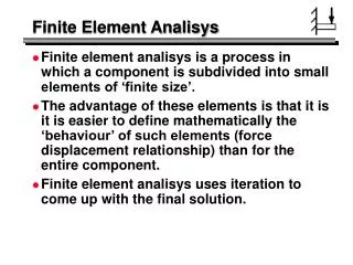
The Finite Element Method (FEM) • General technique for constructing approximate solutions to boundary value problems Study of Mesh Refinement EM 360 Fall 2002
How to Generate a Finite Element Model • An input file must be written containing the following two parts: • Model Data: This portion defines the geometry of the model and material properties. • History Data: This portion defines how the model will be loaded and what values should be outputted.
Some Important Factors to Consider • Boundary Conditions • Load Type and Directions • Mesh Refinement Study of Mesh Refinement EM 360, Fall 2002
Some Important Factors to Consider : Mesh Refinement Peterson’s Stress Concentration Factors, 1997 11 Elements 1 Second K=4.342 s ____ max K= s Finite Element Study of Structural Discontinuities, 2003
Some Important Factors to Consider : Mesh Refinement 67 Elements 1 second K=4.41 Finite Element Study of Structural Discontinuities, 2003
Some Important Factors to Consider : Mesh Refinement 211 Elements 1 second K=4.47 Finite Element Study of Structural Discontinuities, 2003
Some Important Factors to Consider : Mesh Refinement 823 Elements 2 seconds K=4.512 Finite Element Study of Structural Discontinuities, 2003
Some Important Factors to Consider : Mesh Refinement Approx. 3000 Elements 4 seconds K=4.517 Finite Element Study of Structural Discontinuities, 2003
Some Important Factors to Consider : Mesh Refinement Approx. 19000 Elements 21 seconds K=4.520 Finite Element Study of Structural Discontinuities, 2003
Mesh Convergence Curve Finite Element Study of Structural Discontinuities, 2003
Computation Time Finite Element Study of Structural Discontinuities, 2003
Mesh Convergence • Refining a coarse finite element mesh will result in a more accurate solution at the cost of computation time.
Caveat and Approach • Just because a solution is obtained does not necessarily mean it is correct. Therefore, it is important to study the results and compare your solution with a known, correct solution.
Previous Work Peterson’s Stress Concentration Factors, 1997 • Model 1 Finite Element Study of Structural Discontinuities, 2003
Previous Work • Model 1 (continued) Finite Element Study of Structural Discontinuities, 2003
Previous Work Peterson’s Stress Concentration Factors, 1997 • Model 2 Finite Element Study of Structural Discontinuities, 2003
Previous Work • Model 2 (continued) Finite Element Study of Structural Discontinuities, 2003
New Work • Reduction of stress concentrations from edges of holes • Finite element modeling of cracks • Reduction of crack stress intensity factor
Reducing Stress Concentrations from Holes • Method:Add another hole to alleviate the stress concentration. • Constant: Radius of original hole = 2 in Tensile Load = 1 psi in horizontal direction • Variables: R = radius of added hole L = distance between centers of holes
Reducing Stress Concentrations from Holes Finite Element Study of Structural Discontinuities, 2003
Reducing Stress Concentrations from Holes Finite Element Study of Structural Discontinuities, 2003
Reducing Stress Concentrations from Holes Finite Element Study of Structural Discontinuities, 2003
Reducing Stress Concentrations from Holes Finite Element Study of Structural Discontinuities, 2003
Reducing Stress Concentrations from Holes • Conclusion: Adding holes in a plane perpendicular to the loading direction does not reduce the stress concentration factor.
Reducing Stress Concentrations from Holes Finite Element Study of Structural Discontinuities, 2003
Reducing Stress Concentrations from Holes Finite Element Study of Structural Discontinuities, 2003
Reducing Stress Concentrations from Holes Finite Element Study of Structural Discontinuities, 2003
Reducing Stress Concentrations from Holes Finite Element Study of Structural Discontinuities, 2003
Reducing Stress Concentrations from Holes Finite Element Study of Structural Discontinuities, 2003
Reducing Stress Concentrations from Holes Finite Element Study of Structural Discontinuities, 2003
Reducing Stress Concentrations from Holes Finite Element Study of Structural Discontinuities, 2003
Reducing Stress Concentrations from Holes • Conclusion: Adding holes in a plane parallel to the loading direction does reduce the stress concentration factor.
Finite Element Analysis of Cracks • Crack configuration models: Tada The Stress Analysis of Cracks Handbook Model 1 Model 2 Model 3
Finite Element Analysis of Cracks Crack Model 1 (Center Cracked Plate)
Finite Element Analysis of Cracks Crack Model 2 (Edge Cracked Plate)
Finite Element Analysis of Cracks Crack Model 3
Finite Element Analysis of Cracks Tada, The Stress Analysis of Cracks Handbook Crack Model 3
Finite Element Analysis of Crack Repair • Crack repair models: Finite Element Study of Structural Discontinuities, 2003
Finite Element Analysis of Cracks Center Cracked Plate with Stop Holes
Finite Element Analysis of Cracks Center Cracked Plate with an Array of Holes Near the Crack Tip
Finite Element Analysis of Cracks Patch Repair of Center Cracked Plate