Download
1 / 2
20 likes | 234 Views
THE CERN SPL CHOPPER CONCEPT AND FINAL LAYOUT F. Caspers , Y. Cuvet, J. Genest, M. Paoluzzzi, A. Teixeira CERN, Geneva, Switzerland. Abstract

E N D
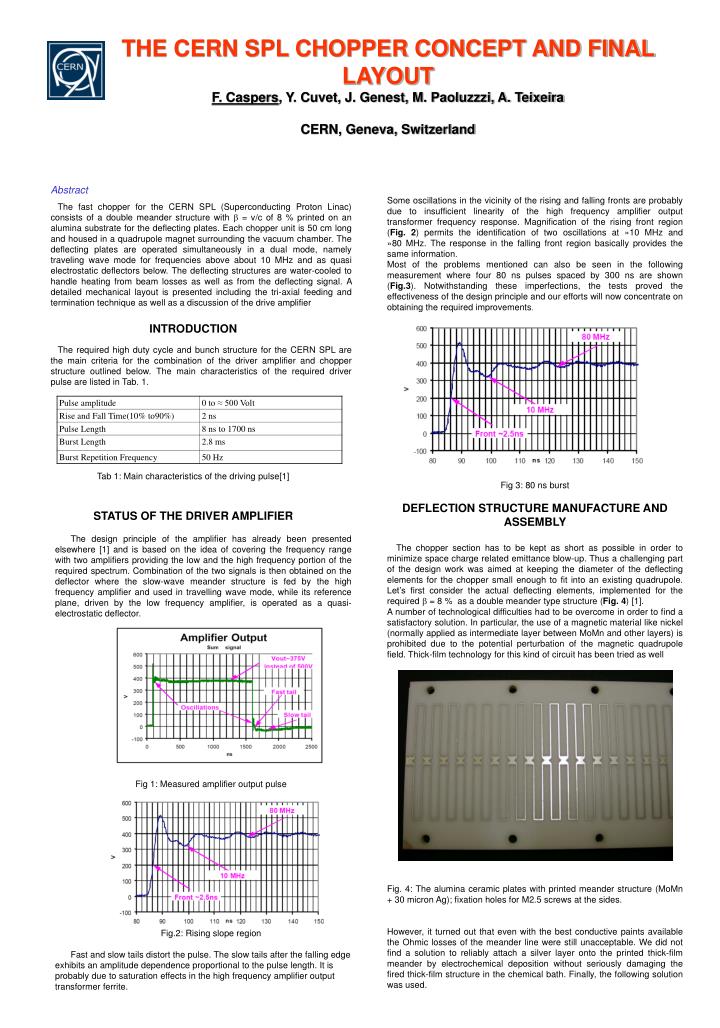
THE CERN SPL CHOPPER CONCEPT AND FINAL LAYOUT F. Caspers, Y. Cuvet, J. Genest, M. Paoluzzzi, A. Teixeira CERN, Geneva, Switzerland • Abstract • The fast chopper for the CERN SPL (Superconducting Proton Linac) consists of a double meander structure with b = v/c of 8 % printed on an alumina substrate for the deflecting plates. Each chopper unit is 50 cm long and housed in a quadrupole magnet surrounding the vacuum chamber. The deflecting plates are operated simultaneously in a dual mode, namely traveling wave mode for frequencies above about 10 MHz and as quasi electrostatic deflectors below. The deflecting structures are water-cooled to handle heating from beam losses as well as from the deflecting signal. A detailed mechanical layout is presented including the tri-axial feeding and termination technique as well as a discussion of the drive amplifier • INTRODUCTION • The required high duty cycle and bunch structure for the CERN SPL are the main criteria for the combination of the driver amplifier and chopper structure outlined below. The main characteristics of the required driver pulse are listed in Tab. 1. • Tab 1: Main characteristics of the driving pulse[1] • STATUS OF THE DRIVER AMPLIFIER • The design principle of the amplifier has already been presented elsewhere [1] and is based on the idea of covering the frequency range with two amplifiers providing the low and the high frequency portion of the required spectrum. Combination of the two signals is then obtained on the deflector where the slow-wave meander structure is fed by the high frequency amplifier and used in travelling wave mode, while its reference plane, driven by the low frequency amplifier, is operated as a quasi-electrostatic deflector. • Fig 1: Measured amplifier output pulse • Fig.2: Rising slope region • Fast and slow tails distort the pulse. The slow tails after the falling edge exhibits an amplitude dependence proportional to the pulse length. It is probably due to saturation effects in the high frequency amplifier output transformer ferrite. Some oscillations in the vicinity of the rising and falling fronts are probably due to insufficient linearity of the high frequency amplifier output transformer frequency response. Magnification of the rising front region (Fig. 2) permits the identification of two oscillations at »10 MHz and »80 MHz. The response in the falling front region basically provides the same information. Most of the problems mentioned can also be seen in the following measurement where four 80 ns pulses spaced by 300 ns are shown (Fig.3). Notwithstanding these imperfections, the tests proved the effectiveness of the design principle and our efforts will now concentrate on obtaining the required improvements. Fig 3: 80 ns burst DEFLECTION STRUCTURE MANUFACTURE AND ASSEMBLY The chopper section has to be kept as short as possible in order to minimize space charge related emittance blow-up. Thus a challenging part of the design work was aimed at keeping the diameter of the deflecting elements for the chopper small enough to fit into an existing quadrupole. Let’s first consider the actual deflecting elements, implemented for the required = 8 % as a double meander type structure (Fig. 4) [1]. A number of technological difficulties had to be overcome in order to find a satisfactory solution. In particular, the use of a magnetic material like nickel (normally applied as intermediate layer between MoMn and other layers) is prohibited due to the potential perturbation of the magnetic quadrupole field. Thick-film technology for this kind of circuit has been tried as well Fig. 4: The alumina ceramic plates with printed meander structure (MoMn + 30 micron Ag); fixation holes for M2.5 screws at the sides. However, it turned out that even with the best conductive paints available the Ohmic losses of the meander line were still unacceptable. We did not find a solution to reliably attach a silver layer onto the printed thick-film meander by electrochemical deposition without seriously damaging the fired thick-film structure in the chemical bath. Finally, the following solution was used.
Fig. 5: Alumina ceramic plates on water cooled metal support structure Fig 6 Chopper structure suspension concept Fig. 7: Complete chopper with vacuum tank mounted in a quadrupole CONCLUSIONS AND OUTLOOK The present version of the SPL chopper system looks promising despite some remaining technical issues, in particular on the driver side. Due to the challenging operating requirements new frontiers in amplifier technology had to be explored. Also for the deflecting plates interesting technological problems had to be solved. We expect to carry out power, RF and high voltage tests on the final prototype in a few months from now. ACKNOWLEDGEMENTS The authors would like to thank R. Garoby for many enlightening discussions and support, M. Malabaila for having done the delicate chemical treatments as well as R. Teuchner (Wesgo/Erlangen) for helpful comments and timely delivery of the ceramic. We acknowledge the support of EU through the CARE I3, contract number RII3-CT-2003-506395. REFERENCES [1] M. Paoluzzi, Design and performance of a 500V pulse amplifier for the chopper of the CERN superconducting H- linac (SPL), EPAC 2002, Paris, (CERN/PS 2002-026-RF) [2] F. Caspers, A. Mostacci, S. Kurennoy, Fast Chopper Structure for the CERN Superconducting Proton Linac, EPAC 2002, Paris, (CERN-PS- 2002-027-RF) SILVER COATING OF THE CHOPPER PLATE The ceramic plate (400*60 mm2) arrives from the manufacturer (Wesgo in Erlangen/Germany) with one side covered by a homogeneous MoMn layer. This type of ceramic-metal bond was selected for best mechanical stability of the base layer. During production the MoMn paste is fired at 1500 °C in a H2/N2 atmosphere onto the ceramic plate resulting in a layer thickness between 12 and 20 micron. The ceramic material used here is AL300 with a purity of 97.6 % and 1.6 micron surface roughness. The processing at CERN starts with sputter etching to clean the surface during two minutes with a D.C. power of 50 W in an argon atmosphere of 1*10-1 mbar. The plate is the coated with two different layers in vacuum by magnetron sputtering. The coating system is equipped with two planar magnetron sources of Ø 150 mm. 24 hours of pumping and a bake-out at 150 ºC result in a final pressure of 5*10-9 mbar. To increase the adherence of the silver layer, an intermediate layer of 0.5 µm titanium is deposited at an argon pressure of 1.1*10-3 mbar. Earlier tests without sputter etching and titanium, and a process with sputter etching only, did not give good adherence. Sputter etching needs to start with a clean surface and the titanium is necessary for a better “crystallographic” compatibility with MoMn. Directly sputtering silver onto the MoMn results in poor adherence despite all surface cleaning efforts. A final layer of 2 µm silver was deposited on top of it with the same argon pressure. During these two coating runs the plate is moved in front of the sources several times in order to obtain a uniform coating thickness. Byelectrochemical deposition this silver layer is increased later up to 30 µm. The subsequent chemical etching procedure applies in principle the usual photo resist technique and chemically removes the undesired surfaces of the yet homogeneously coated ceramic plate. However, the presence of 3 different metals (silver, titanium, MoMn) to be removed requires three different chemical baths (Iron–nitrate; fluorhydrid acid and nictric-acid/sulphuric-acif for the MoMn). ASSEMBLY OF THE DEFLECTING PLATES INTO A UHV TANK As shown in Fig. 5 the ceramic plates with the meander structure facing the beam are mounted onto a water-cooled aluminium support structure. This is done using a number of small screws with a very soft washer and considerable tolerance of the hole diameter to avoid any strain in the ceramic. Note that the rear side of the ceramic plates is not metal-plated and that the aluminium plate serves as ground plane. There have been concerns that this kind of structure may lead to vacuum problems, but very similar circuits have been used in the CERN AA (antiproton accumulator). No vacuum drawbacks were noticed down to 10-11 Torr (with in-situ bake-out). In Fig 6 the basic support concept of chopper plates and the mounting concept is depicted. Finally we see in Fig 7 the complete vacuum tank with the deflecting plates (mounted on isolating ceramic supports) and the tri-axial feed-throughs. Note that the water-cooling circuits contain also electrically isolating elements in order to permit a static potential on the metallic supports of the ceramic plates. The vacuum tank is surrounded by the quadrupole magnet.