Download
1 / 53
530 likes | 769 Views
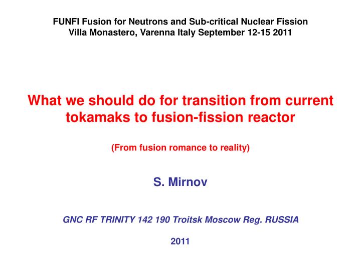
FUNFI Fusion for Neutrons and Sub-critical Nuclear Fission Villa Monastero, Varenna Italy September 12-15 2011 What we should do for transition from current tokamaks to fusion-fission reactor (From fusion romance to reality) S. Mirnov GNC RF TRINITY 142 190 Troitsk Moscow Reg. RUSSIA 2011.

E N D
FUNFI Fusion for Neutrons and Sub-critical Nuclear Fission Villa Monastero, Varenna Italy September 12-15 2011 What we should do for transition from current tokamaksto fusion-fission reactor (From fusion romance to reality) S.Mirnov GNC RF TRINITY 142 190 Troitsk Moscow Reg. RUSSIA 2011
Introduction. Requirements shown by Russian atomic engineers to the parameters FNS-1 1.Decision of steady state tokamak operations. The superconductor and warm magnets systems Current drive. 2.The problem of plasma-wall interaction Phenomenological limit of power load on tokamak first wall. The neutron flux limits in FNS-1. Lithium as a tokamak PFC protector 3.Creation of hot plasma zone with high neutron emission The control of plasma density Impurity control in the center of tokamak plasma 4. Other candidates on the role of fusion neutron source type of FNS-1 The mirror traps (GDT) Stellarators (LHD) Superconductor tokamaks (Tor Supra, EAST, KSTAR) Spherical torus.(NSTX, MAST) Conclusions
Fusion-Fission roots in Russia 1956 Sakharov A. Memoirs Vintage Books, New York (1990) 142 I.N.Golovin, V.I.Pistunovich, G.E.Schatalov Preprint IAE 1973 Physical basis of tokamak-reactor with NBI (First hybrid FF) I.N.Golovin, G.E.Schatalov, B.N.Kolbasov. Isvestiya AS USSR 1975 Energy and transport № 6 p28-34. . USA/USSR Symposium on Fusion-Fission Reactors, Lawrence Livermore Laboratory CONF-760733 July 13-16 1976. USSR/USA Seminar 14March-1April 1977 M Atomisdat 1978
τE, 98 = 0,0365.Iр0,97.BТ0,08.PH-0,63.n0,41.M0,20.R1,93.(a/R)0,23.k0,67sec ITER Physics basis. Nuclear Fusion v39 N12 1999 Progress in ITER Physics basis. Nuclear Fusion v47 N6 2007
Potential using of fusion-fission in the electricity production (for Russia)
Joint commission of 2009Y :Plasma physicists (TRINITI, KURCHATOV, IOFFE Inst.) and Atomic engineers (DOLLEJAL, KURCHATOV Inst. suggested the three steps scheme of Russian FNS development
Creation of the hydrogen TNS prototype – TNS-0 on the T-15 basis for the investigation of steady state tokamak physics • 2. Creation of the tokamak- breeder prototype – TNS-1 - with neutron power 20-50MW and fuel production equal 20-100 kg p/y • (2020-2025yy) • 3.Creation of the commercial tokamak- breeder prototype – TNS-2 with neutron power 100-200MW and fuel production up to 1000 kg p/y • (2025-2035yy)
The Russian fission community has madespecial requirements to the fusion neutron source FNS-1 for the first step of investigation. • quasi-steady state (with availability Kt >80%) DT fusion reactor operation • surface neutron load pnnot lower 1017n/m2sec (0.2MW/m2) • total neutron output not lower Pn=20MW. • The main aims of FNS-1 : • demonstration of industrial probabilities of such neutron source, with ability of nuclear fuel producing on the level 100kg for the test of different versions of experimental blanket modules. • (So called “ Lopatkin’s requirements” at name of deputy director of Dollejal institute A.V.Lopatkin ) • Middle-scale device with the total cost not higher than $1bn. • No activity in direction of sub-critical Nuclear Fission from safety problem.
What we should do for transition from current fusion devicesto FNS-1?
Comparison of the total neutron energy production Qn per day: for FNS-1, ITER (project), JET (should be multiplied up to 2000 timesdotted array– proposal steady state operational regime), and NIF (proposal regime, should be multiplied up to 200000 times)
The creation of FNS-1 on the basis of a warm magnets system (Cu, Al) is considered with superconductor if one takes into account that a limited time period (about 1 year ) will be sufficient for the FNS-1main task – production of 100kg of fuel by a steady- state fast neutron source with the total neutron power not lower than 20MW and density 0.2MW/m2. Within this time the system will accumulate in its units the relatively low neutron fluency (3 1024n/m2). The 30% of such neutron fluency will be enough for production of the planned 100 kg of fuel
Magnet (Cu) system of VNS-1 project (TRINITI-Kurchatov 1993Y) 1-poloidal, 2-toroidal Cu coils. 3-concret tank a/R=0.7/2 m, B0 =3.5T, Jp =4MA P=300MW
The problem of plasma-wall interactionPhenomenological limit of power load on the tokamak first wall
A-dynamics of neutron production- Pfus B-PH in linear scale, crosses and PH, - PH/S.
The tokamak praxis shows the existence of rather hard phenomenological limit of power load on the tokamak first wall qc ≈0.2±0.1МW/m2 What happened after the violation of this limit?
TFTR . Evolution of DT fusion power and plasma stored energy for a series of plasmas with mixed D and T NBI. One or two lithium pellets were injected into the plasma prior to NBI.
This limit will confine the maximum value of the neutron flux density pn on the first wall of the tokamak-reactor. In the most favorable case of burning tokamak the relation between the total power of neutron production Qn to the plasma heating power by α-particles PH (as is known) is equal to 4. It means that for the burning reactor type DEMO limit qc= 0.2МW/m2 is equivalent to limit pn=0.8МW/m2 This limit seems too low for a pure fusion reactor, but not for a fusion-fission one. For example, the fusion-fission burning tokamak scale ITER with natural uranium blanket can produce up to 3GW electric power and at the same time produce the fuel for fission reactors needed for generation additional 10GW of electricity.
In FNS-1 case the situation is complicated by the fact that two sources of fast neutrons should be used in it (as in burning tokamak). The FNS-1 has two neutron producers – one part of neutron output should be generated during the direct interaction of high energy ion beam (100-300keV) with the target - DT (1:1) tokamak plasma (QBF) The second part should be the result of DT fusion in the hottest target plasma (QTF). In real prototypes of FNS-1 – TFTR and JET both these fusion sources were considerable.
In the steady state conditions the total heat flux to the first wall will be the summary results of both sources of fusion α-particles and NBI power. If we write QBF as αРН , where α is function, connected NB power PH with fusion output from direct interaction of ion beam with target plasma, the summary neutron output can be written, as Qn= 0.8(αРН+ QTF) and power of total heat flux as РН + 0.2 (αРН + QTF). That means: pn/q = 0.8(α + QTF/РН)/ (1 + 0.2 (α+ QTF/ РН)) For burning tokamak (PH=0) we have again pn/q =4. For the opposite case QTF =0 (case of “pure target”) pn/q = 0.8α / 1 + 0.2α
The calculated αvalues as function of electron temperature Te for different energies of injected D-atoms to the clean (Zeff ≈1) DT (1:1) target plasma (V.I. Pistunovich 1976)
The achievement of values α ≈1 in average-scale tokamaks seems realistic. In this case pn/q from can be 0.67 and if we take into account the limit qc = 0.2МW/m2, the pn value should be equal 0.13 МW/m2, which is lower of neutron density requirements 0.2МW/m2 for FNS-1.It is obvious that in order to increase the neutron load tokamak with visible QTF output should be chosen. In particular, with QTF/РН = 1 the pn value can be increased up to 0.26 МW/m2.
Another possible way is increasing qc by mitigation of heat contact plasma-wall effect.It is known that the most aggressive form of such contact is the first wall bombardment by hot plasma during development of plasma boundary instabilities (ELMs, Blob’s) with high local energy loads and, as a result, with active erosion of the first wall materials. To smooth the local energy loads some experimentalists try to reradiate plasma energy flux by injecting radiated impurities into the plasma periphery. The role of such kind impurity can play Li. It should be pointed out that Li pellet injection was actively used in TFTR
J.Bohdansky and J.RothTemperature dependence of sputtering behavior of Cu-Li alloysNucl. Instr.and Methods in Physics Research B23 (1987) 518
The main surprise of numerous tokamak lithium experiments was the discovery of the poor lithium penetration to the hot core from plasma periphery (lithium screening). The effective ion charge in plasma center - Zeff(0) which had been equal to 2 or higher (TFTR, T-11M, FTU, T-10, CDX-U,) dropped down to 1 after first wall lithiaton. The mechanism of lithium screening is not fully clear. Probably that is consequence of deep gap between lithium first (5.8eV) and second (75eV) ionization potentials. The lithium screening effect can be served as a basis of concept of permanent lithium circulation close the tokamak first wall for their protection from the direct plasma bombardment
FTU experiment. Li CPS limiter after plasma exposition No Surface Damage
Li migration by CPS W CPS
Creation of hot plasma zone with high neutron emissionThe control of plasma density
The record TFTR DT shot with NBI PH= 40MW ( PH/S=q ≈0.5MW/m2, pnmax ≈0.12MW/m2)
In steady state tokamak all fluxes of neutral atoms in the plasma column should be balanced by their outward diffusion, neutralization and pumping.The atoms of NBI and He should be removed by the divertor with expanded divertor plates (for example, by “snowflake” type) probably with lithium coating. For the He pumping and creation of Li-circulation in divertor SOL a mushroom like pump limiter shown in could be used.
The mushroom like pump limiter for the He pumping and creation of Li-circulation in divertor or limiter SOL
As is shown by the experience of ECRH use in small and average – scale tokamaks, the local ECRH permits not only increasing Te, which increases the fast ion relaxation time but also promoting impurity removal from plasma center and increasing the diffusion of DT ions. It is supposed to stabilize Zeff in plasma center on the level of 1-1.2, which is needed for achievement of α≈1.The next way of the α increase (Fig.5) can be bringing up the energy of the injected atoms from 110-120keV (TFTR, JET) up to 150keV.
Other candidates on the role of fusion neutron source type of FNS-1The mirror traps (GDT)Stellarators (LHD)Superconductor tokamaks (Tor Supra, EAST, KSTAR)Spherical torus.(NSTX, MAST)
The comparison of different types of magnetic fusion devices as candidates on the role of FNS-1
Spherical torus. Jp≈(5εaB0/qψ(95%))[1+k2(1+2δ2-1.2δ3)] (1.17- 0.65ε)/(1-ε2)2 /2, The formal substitution in this equation ε = 0.7-0.8 and best parameters of high performers “classical” (ε<0.4) tokamaks - qψ(95%)=3, k=3, δ=0.8 3, k=3, -gives the above mentioned profit in Jp up to 3-5 times. That is a mistake. The right side of this equation consists of two kinds of parameters. Their first part seems independent, hard determined by experimentalist. That is ε, a, B0, which are the “material” condition of experiment defined its scale and cost. The second group of “plasma connected parameters” - qψ(95%), k and δ seems as internal depended.
. Really each experimentalist should find an optimal combination of these parameters with the main goal to obtain the maximal plasma current. If this combination is universal, the maximal Jpmах should be proportional εaB0(1.17- 0.65ε)/(1-ε2)2,
The maximal values of Jp, received on 4 leaded spherical torus – as function of εaB0 (1.17- 0.65ε)/(1-ε2)2 [14-19], cross NSTXnew (B0=0.3T, Jp=1MA) – private communication
The next serious disillusion was brought by the unexpected effect of spontaneous breaking of discharges in spherical torus, which was observed simultaneously in both leaded devices – NSTX and MAST. The nature of this effect is not yet clear today. Probably that is effect, connected with too high βТ in spherical torus. As a result, the shot duration was limited in these devices by 1-1.8 sec instead of 5sec, proposed by projects. That means the spherical torus with ε = 0.7-0.8 lost the main advantage of tokamaks – the potential ability of steady state operations.
NSTX and MAST- effect of discharge interruptionJ.E.Menard, M.G.Bell,e.a. Proc.21st IAEA Fusion Energy Conf., Chengdu, China, 2006 OV/2-4.