1 / 0

electrical Loads

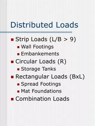
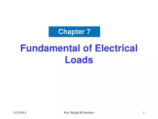
An- Najah National University Faculty of Engineering Electrical Engineering Department. electrical Loads. the first step in the electrical designing for any construction is to estimate the electrical loads

dore
Download Presentation

electrical Loads

An Image/Link below is provided (as is) to download presentation Download Policy: Content on the Website is provided to you AS IS for your information and personal use and may not be sold / licensed / shared on other websites without getting consent from its author. Content is provided to you AS IS for your information and personal use only. Download presentation by click this link. While downloading, if for some reason you are not able to download a presentation, the publisher may have deleted the file from their server. During download, if you can't get a presentation, the file might be deleted by the publisher.

E N D

Presentation Transcript


  1. An-Najah National University Faculty of Engineering Electrical Engineering Department

    electrical Loads

    the first step in the electrical designing for any construction is to estimate the electrical loads This enables the electrical engineering (designer) to know exactly who should the electrical power feed this construction
  2. An-Najah National University Faculty of Engineering Electrical Engineering Department

    Electrical Loads

    Electrical loads in the buildings can be divided into three types:- Electrical loads used in lighting ( illumination system) , different types of lamps) Electrical loads feed the normal sockets and outlets ( used for small electrical devices , TV, radio , washing machine, etc….) Electrical loads that feed the mechanical devices used in the buildings ( elevators , heating system ,cooling system , pumps ,etc)
  3. An-Najah National University Faculty of Engineering Electrical Engineering Department

    estimation of the electrical loads used in lighting

    the estimation of the electrical loads used in lighting is achieved by calculating the sum of the lamps used in the illumination system there are different types of lamps :- Incandescent Lamp Gas-discharge lamps
  4. An-Najah National University Faculty of Engineering Electrical Engineering Department

    Old method for Electrical Load estimation in lightings

    this methods assumes that all the lighting system consists of either Incandescent Lamp or florescent lamps or a mixed of them . in the case of using incandescent lamps :- Power(watt/m2) = illuminances (Lux)/2.78 in the case of using incandescent lamps :- Power(watt/m2) = illuminances (Lux)/11.148 form the above equations it is quite clear that the using of florescent lamps can save power so it is quite important to use them as much as possible. This method is no longer used as it depends on approximations in addition to the fact that there a lot of different types of lamps used these days
  5. An-Najah National University Faculty of Engineering Electrical Engineering Department

    example

    An office with an area of 60 m2, and the illuminance equals 500 lux, calculate the power needed in the cases of using the incandescent lamp and florescent lamps. Answer :- in the case of using candescent lamps :- P= 60* 500 /2.78709 = 10763 watt in the case of using florescent lamps : P= 60* 500 /11.148 = 2691 watt power saving using the florescent lamps= 10763-2691= 8072 watt
  6. An-Najah National University Faculty of Engineering Electrical Engineering Department

    Unit or Specific Load per Square meter

    To over come the disadvantage of the previous method the “Unit or specific load per square meter” which depends on the natural using of the space in the building. This method give more accurate results than the previous one.
  7. An-Najah National University Faculty of Engineering Electrical Engineering Department
  8. An-Najah National University Faculty of Engineering Electrical Engineering Department

    ways for energy consumption saving in lights systems

    using lamps unites with high efficiency which is called “energy saving lamps” which have a high efficiency per watt in addition to the fact that they lasting for long times compared to the normal lamps using lamps unites with low electrical losses on the form of heat which reduce the need of using the cooling systems for the construction. reducing the light losses by using lamp units with low light losses coefficient using lamp units with higher coefficient utilization
  9. An-Najah National University Faculty of Engineering Electrical Engineering Department

    Unit Power density procedure

    this method differs than the previous methods in:- 1- it takes into account the shape of the rooms or the space(square,rectangle, etc) 2- it assumes that the lighting system in that room or space is based on the maximum using of the electrical power. This method depends on dividing the building into rooms depending on the nature of using. And for every room or space there is a tables shows base power unit density(UPD) for that space in watt/m2
  10. An-Najah National University Faculty of Engineering Electrical Engineering Department

    Unit Power density procedure

    the power needed for lighting a room or a space according to this method is:- Power= Area* Power unit density(UPD)*room factor* space utilization factor(SUF). Power= A* a1* a2 Power: watt Area (A):m2 Power Unit density(UPD): (F):watt/ m2 Room factor : (a1) Space utilization factor :(a2)
  11. An-Najah National University Faculty of Engineering Electrical Engineering Department

    Unit Power density procedure

    Power Unit density(UPD): obtained from tables(1.2)
  12. An-Najah National University Faculty of Engineering Electrical Engineering Department

    Unit Power density procedure

    Room factor : (a1) Room factor (a1) is a number between 1.0 and 2.0 and its important comes from that it shows the effect of the room or space shape on the lighting system . From table (2.2) Eg 1 :- length of the room is 2.4 . Width is 3.7 and the length is 2.7. the room factor from the table will be 1.8 Eg 2 :- length of the room is 7.3 . Width is 2.4 and the length is 3.4. the room factor from the table will be 1.9 If the shape of the room is not regular we choose a nearest regular shape such that the area of the regular shape is equal to the irregular shape of the room or space
  13. An-Najah National University Faculty of Engineering Electrical Engineering Department

    Unit Power density procedure

    Space utilization factor :(a2) The value of the space utilization factor (S.U.F) is between 0.4 and 1.0 . it is depends on the ration between the area of the room or space that is used and the total area of the space or the room.
  14. An-Najah National University Faculty of Engineering Electrical Engineering Department

    Unit Power density procedure

    Unlisted areas After calculating the electrical power needed for lighting the rooms it means that we calculate the electrical power needed for lighting all the listed areas. For the unlisted spaces . First : the area of these spaces are calculated and it equals the area of each flat in the building –the area of the listed spaces. The electrical power for the unlisted spaces is then calculated by multiplying its area by 2.15 watt/m2 the total electrical power for lighting the inner area will be sum of the powers needed for listed and unlisted area.
  15. An-Najah National University Faculty of Engineering Electrical Engineering Department The maximum electrical power for the whole building

    Unit Power density procedure

    it consists of 1- the electrical power calculated for the inner space of the project(listed and un listed) 2- the electrical power needed for lighting the outside of the project a- the electrical power needed for lighting the outside walls of the project (5% of the electrical power needed for the inner lighting ) b- the entrance of the building and the exit (table 1.2) Unit power density for the inner lighting of the project= power for inner light/ total area of the flats Unit power density for the lighting of the project= power for inner light/ total area of the project
  16. An-Najah National University Faculty of Engineering Electrical Engineering Department The maximum electrical power for the whole building

    Unit Power density procedure

    after calculating the total power for the whole building we multiply this power by factor called demand factor which equals 0.85 in the case of lighting. Unit power density for the inner lighting of the project= power for inner light/ total area of the flats Unit power density for the lighting of the project= power for inner light/ total area of the project
  17. An-Najah National University Faculty of Engineering Electrical Engineering Department

    Electrical loads needed for feeding the sockets and outlets

    used to feed electrical devices with small power if the devices that connected with socket is already known, then the rated power for that device is considered. if not , then for each socket , we assume that the power for the devices that connected to that socket is between 200 to 250 watt if it is single If it is double socket then we assume the power for that socket is about 350 watt.
  18. An-Najah National University Faculty of Engineering Electrical Engineering Department

    Electrical loads needed for feeding the sockets and outlets

    Table 5.1 shows the number of sockets needed in each room in the building Form the table the number of sockets needed in kitchen is 4 in addition to a special socket for the cooker unit. The total power needed for feeding the sockets will be then multiply by 0.7 as a demand factor.
  19. An-Najah National University Faculty of Engineering Electrical Engineering Department

    Electrical loads needed for feeding the mechanical devices

    Conditiong unit :- each ton refrigeration needs 1500 watt electrical power. Table 6.1 shows the number of ton refrigerating needed in different types of buildings For the pumps :- the electrical engineering obtained the mechanical Horsepower (HP) needed for each pumps The electrical power =for that pump will be: mechanical Horsepower *746 watt For the Escalator and Electrical Stair the power will be given from the catalogue
  20. An-Najah National University Faculty of Engineering Electrical Engineering Department

    Electrical lamps

    Electrical lamps that used in lighting is divided into two main type:- 1- Incandescent lamps 2- Discharge lamps For the incandescent lamps :- the light is emitted as a result of electrical current passing through a filament , which makes it heated to a high temperature then glowing and luminating . For the discharge lamps:- the light is emitted due to the glowing of the gas atoms between the poles of the lamp.
  21. An-Najah National University Faculty of Engineering Electrical Engineering Department The luminous efficacy of a lamp

    Electrical lamps

    Specification of electrical lamps:- 1- Luminous flux (lumen) 2- Luminous efficiency ( Lumen/watt) 3- Life time 4- Illumination (Lux) or (Lumen/m2) 5- power , voltage (watt ,V) 6- size of the lamp
  22. An-Najah National University Faculty of Engineering Electrical Engineering Department The luminous efficacy of a lamp

    Electrical lamps

    Incandescent lamps 1 – Filament (Tungstun) 2- Bulb 3- Base 4- inert gas or empty volume
  23. An-Najah National University Faculty of Engineering Electrical Engineering Department The luminous efficacy of a lamp

    Electrical lamps

    Incandescent lamp the current is fed from the electrical source to the filament using the base when the current pass through a filament, its temperature is increased and after a short time it is becomes glowing and emitting the light. carbon used to be used in the filament , but now a days , Tungstun is used in filament and sometimes some elements such as AL, K, SI are added to Tunstun to improve the hardness of the filament luminous efficiency of the incandescent lamps increases as power of that lamps increase . For example, a lamp with power 150 watt give more illumination in a percentage of 34% than using three 50 watt lamps.
  24. An-Najah National University Faculty of Engineering Electrical Engineering Department The luminous efficacy of a lamp

    Electrical lamps

    Incandescent lamp the tungstun incandescent lamps are used a lot because of:- 1- it is found in a lot of shapes (table 2.3) 2- the quality of light (suitable for the eye) 3- is very cheap The lifetime for the incandescent is about 1000 hour, The luminous flux of the incandescent lamps is directly related to the applied voltage on the lamp. Table 3.3 shows the relation between the luminous flux , voltage, and the lifetime .
  25. An-Najah National University Faculty of Engineering Electrical Engineering Department The luminous efficacy of a lamp

    Electrical lamps

    Incandescent lamp The end life of the Tungstun lamps The melting of the filament is the indication of the end life of the Tungstun incandescent lamps Due to a defect in a position on the filament , a hot-spot is formed on it, and the temperature of the on that position at beginning will be higher than other position on the filament. the high temperature makes the Tungstun to evaporate. All these process happened at the beginning of the lighting . The evaporated Tungstun is stuck on the inner surface of the bulb making a black colour to appears on the bulb surface.(blackening).
  26. An-Najah National University Faculty of Engineering Electrical Engineering Department The luminous efficacy of a lamp

    Electrical lamps

    Incandescent lamp The end life of the Tungstun lamps The blackening phenomena appears only in the Tungstun lamps where the bulb is evacuated from the air To overcome the blackening phenomena , a Halogen Lamps are used where one of the following halogen is used (Cl, Br, I, F) in addition to the inert gas. This halogen helps to return back the evaporated Tungstun. they are more efficient than incandescent bulbs using only half the energy to produce the same light output and last twice as long The halogen lamps are used for specific applications where a low voltage and clear light is needed like , cinema , projectors, theaters, cars lamps , in TVs
  27. An-Najah National University Faculty of Engineering Electrical Engineering Department The luminous efficacy of a lamp

    Electrical lamps

    Discharge lamps the principal operation of the discharge lamps is based on an electrical discharge in the atoms of the inert gas or the vapour of metals or a mixed of them. this results on some visible lights It is divided into two types:- 1- low pressure discharge lamps (Neon , Florescent) 2- high pressure discharge lamps (Soduimand mercury )
  28. An-Najah National University Faculty of Engineering Electrical Engineering Department Florescent lamps

    Electrical lamps

    The current passes through the circuit heating up the filament in each electrode, which are located at both ends of the tube. The heated electrodes in addition to the high voltage applied to two ends of the lamps cauasing electrical discharge (ionizing the gas(argon)). The mercury vapor becomes "excited" and it generates radiant energy, mainly in the ultraviolet range. This energy causes the phosphor coating on the inside of the tube to fluorescent, converting the ultraviolet into visible light.
  29. An-Najah National University Faculty of Engineering Electrical Engineering Department Florescent lamps

    Electrical lamps

    in order to obtain a light from florescent lamps, the following things should be happened 1- electrical discharge 2- tranforming the ultraviolet radiated energy to a visible light
  30. An-Najah National University Faculty of Engineering Electrical Engineering Department

    Electrical lamps

    Power of the lamps(watt) Incandescent lamps 1- general service lamps (15 to 250 watt) 2- projectors (40-1000) watt 3- halogen Lamps (1000-2000) watt 4- table lamps for specific use (15- 50)watt (positional use) Florescent lamps 1- general (15-80) watt 2- special types (125-200) watt 3- table lamps (4-31) watt (positional use)
  31. An-Najah National University Faculty of Engineering Electrical Engineering Department

    Electrical lamps

    Mercury Lamps 1- general (80-1000) watt Soduim Lamps 1- low pressure (35-180) watt 2- high pressure (70-1000) watt
  32. An-Najah National University Faculty of Engineering Electrical Engineering Department Lifetime

    Electrical lamps

    Incandescent Lamps :- 1- Genral (1000 ) hour 2- projector (750-1500) hour 3- Halogen (2000) hour Florescent :- 1- (15-80 ) watt :- 1000 hour 2- (125-200) watt:- 3000 hour 3- (4-13) watt:- 2000 hour Mercurry :-7500 hour Soduim :- 2000 hour CFL :- (5000 -15000)
  33. An-Najah National University Faculty of Engineering Electrical Engineering Department

    Electrical lamps

    Luminous efficiency ( Lumen/watt)
  34. An-Najah National University Faculty of Engineering Electrical Engineering Department Energy saving Lamps (CFL)

    Electrical lamps

    It is new lamps and comes to replace the traditional lamps (florescent and incandescent) It has the following characteristics:- 1- Low consumption of energy 2- long life time (5000 hour) 3- high luminous efficiency (50 lumen/watt) 4- have a small size.
  35. An-Najah National University Faculty of Engineering Electrical Engineering Department Comparison between incandescent lamps and CFL lamps

    Electrical lamps

    1- Life time 5- Size * incandescent 1000 hour * bigger * CFL 5000 hour * smaller 2- power 6- weight * incandescent :75 watt * bigger * CFL : 18 watt * smaller 3- luminous flux :- 7- cost * incandescent : 900 lumen * less * CFL : 90 lumen * more 4- luminous efficiency * incandescent : 12 lumen/watt * CFL 50 lumen/watt
  36. An-Najah National University Faculty of Engineering Electrical Engineering Department Comparison between incandescent lamps and CFL lamps

    Electrical lamps

    Eg:- compare between incandescent lamps (75 watt) and CFL lamp with power (18 ) watt . If The price of incandescent is 0.200 JD and the price of the florescent is 4.5 JD and the price of the kwh is 0.04 JD assuming that both kamps will work 5000 hour No of incandescent lamps =5000/1000=5 No if CFL lamps =1 The price of the incandescent lamps =5*0.2 = 1 JD The price of the CFL lamps = 4.5 JD The power consumed by incandescent in 5000 hour in Kwh= 5000 *75/1000 = 375 kwh The price of the kwh = 375 * 0.04 = 15 JD Total for incandescent = 15+1= 16 JD Kwh for CFL = 5000*18/1000= 90 Price of kwh = 90 *0.04= 3.6 JD Total price for CFL = 3.6+4.5 = 8.1 JD Saving = 16- 8.1 = 7.9 JD
  37. An-Najah National University Faculty of Engineering Electrical Engineering Department

    Lighting calculations

    The objective of performing the lighting calculations is to determine the type, power and Distribution the lamps unites This needs the to know the illumination needed in the sapcedepinding on the natural use of the space the method that we want to use here is called Lumen method
  38. An-Najah National University Faculty of Engineering Electrical Engineering Department

    Lighting calculations

    Lumen Method This method depends on using the utilization factor assuming that the illumination is distributed Regularly in all directions in the space. N= Em.A/n*Fl*ku*kn N= no of lamp unites needed to obtain the desired illumination Em= illumination (obtained from tables A = area n= no of lamps in the unite Fl= luminous flux for the lamp (lumen) Ku= utilization factor Kn= maintenance factor
  39. An-Najah National University Faculty of Engineering Electrical Engineering Department

    Lighting calculations

    Lumen Method Kn= maintenance factor The maintenance factor depends on the situation of space :- It is value obtained from the table below:-
  40. An-Najah National University Faculty of Engineering Electrical Engineering Department Lumen Method

    Lighting calculations

    Ku= utilization factor The utilization factor depends on the dimensions of the room .
  41. An-Najah National University Faculty of Engineering Electrical Engineering Department Lumen Method

    Lighting calculations

    Ku= utilization factor Where kr is the room index and it is calculated as follows:- Kr= L*w/Hm(L+w) Where Kr:- room index L :- length of the room w:- width of the room Hm:- the high of the lamp unit from the surface of works in m
  42. An-Najah National University Faculty of Engineering Electrical Engineering Department Lumen Method

    Lighting calculations

    kr If the height of the room is H , and the height of the woorking surface from the ground of the room is Hp, and the lamp unit is hanged a distance HL from the ceiling then Hm=H-HL-Hp Usually Hp = 75 cm except it is given a value different than that.
  43. An-Najah National University Faculty of Engineering Electrical Engineering Department Lumen Method eg

    Lighting calculations

    an office wit dimensions = 8m length , 5 m width and 3 m height . Calculate the number of unit lamps needed for illumination. Solution:- we use lumiluxflourescent lamps from table 16.3 page 111 where luminous flux = Fl=L=3450 lumen . Ilumination =500 lux. Page 275. Maintenance factor=kn= 0.8 Utilization factprkr= L*w/Hm(L+w). HL=0 Hp=0.75 m Hm=3-0-0.75=2.25 m Kr=8*5/(8+5)*2.25=1.37 We choose kr=0.58+0.64/2=0.61 N=500*8*5/2*3450*0.61*0.8=5.59 = 6 units
  44. An-Najah National University Faculty of Engineering Electrical Engineering Department Lumen Method eg

    Lighting calculations

    an office wit dimensions = 8m length , 5 m width and 3 m height . Calculate the number of unit lamps needed for illumination. Solution:- we use lumiluxflourescent lamps from table 16.3 page 111 where luminous flux = Fl=L=3450 lumen . Ilumination =500 lux. Page 275. Maintenance factor=kn= 0.8 Utilization factprkr= L*w/Hm(L+w). HL=0 Hp=0.75 m Hm=3-0-0.75=2.25 m Kr=8*5/(8+5)*2.25=1.37 We choose kr=0.58+0.64/2=0.61 N=500*8*5/2*3450*0.61*0.8=5.59 = 6 units
  45. An-Najah National University Faculty of Engineering Electrical Engineering Department

    Electrical Conductors

    the electrical conductors that are used in electrical installation are usually made from AL or CU or a mixed of them. The difference between the AL and CU is that the specific resistance for the Cu is less than that in AL This means that a cable with bigger radius is needed in the case of AL compared to Cu to conduct the same current.
  46. An-Najah National University Faculty of Engineering Electrical Engineering Department

    Electrical Conductors

    Conductor resistances and the factors that affect it Conductors have a high conductivity due to the existence of a high no of free electrons or in other meanings its electrical resistance is very low :- ρ=1/σ Where ρ is the resistivity and σ is the conductivity of the conductors. The resisivity is an indication of the quality of the materials as the resistivity is wanted to be as small as possible .
  47. An-Najah National University Faculty of Engineering Electrical Engineering Department

    Electrical Conductors

    The resistivity of the conductors is affected by the temperature according to the following formulas:- ρt=ρ0(1+ℓ (T-T0) Where ρtis the resistivity at temperature T ρ0 is the resistivity at 250 ℓ is the thermal expansion coefficient for the conductors at 250
  48. An-Najah National University Faculty of Engineering Electrical Engineering Department

    Electrical Conductors

    thermal expansion coefficient for the conductors
  49. An-Najah National University Faculty of Engineering Electrical Engineering Department The resistance of any cable is given as:- R= ρL/A Where R is the resistance ρ resistivity L length of the cable A area of the cable From the above equations the resistance depends on:- 1-the conductor type (AL ,Cu) 2- length of the cable 3- area of the cable 4- temperature It is meant by temperature :- 1- the temperature of the space around the conductors 2- the temperature of the cable itself which is produced by the current passing in the cable

    Electrical Conductors

  50. An-Najah National University Faculty of Engineering Electrical Engineering Department Ampacity of cables

    Electrical Conductors

    Ampacity is defined as the maximum amount of electrical current which a cable can carry before sustaining immediate or progressive deterioration 1- its insulation temperature rating; 2- the electrical resistance of the cable material; 3-frequency of the current, in the case of alternating current; 4 - ability to dissipate heat, which depends on cable geometry and its surroundings; 5- ambient temperature.
  51. An-Najah National University Faculty of Engineering Electrical Engineering Department How to calculate the cross section area of the cable

    Electrical Conductors

    1- calculate the designing current in the circuit ore part of the circuit 2- according to that , the protection for the circuit is selected 3- the choosing of the cross sectional area of the cable will be according to I cable > I protection > I design
  52. An-Najah National University Faculty of Engineering Electrical Engineering Department Coloures for electrical conductors

    Electrical Conductors

  53. An-Najah National University Faculty of Engineering Electrical Engineering Department

    Electrical Conductors

  54. An-Najah National University Faculty of Engineering Electrical Engineering Department Drop voltage calculations

    Electrical Conductors

    Voltage drop = V1 – V2 =2(I1*r1 +I2*r2+I3*r3+I4*r4) I1,2,3,4 are the currents r1,2,3,4 are the branches resistances Let us assume I1=i1+i2+i3+i4 I2=i2+i3+i4 I3=i3+i4 I4= i4
  55. An-Najah National University Faculty of Engineering Electrical Engineering Department Drop voltage calculations

    Electrical Conductors

    Let us assume R1=r1+r2+r3+r4 R2=r2+r3+r4 R3=r3+r4 R4= r4 Voltage drop = 2(i1*R1+i2*R2+i3*R3+i4*R4) =2∑iαR α As R=ρL/A Voltage drop = 2 ρ/A ∑IL A= (2 ρ/voltage drop) ∑IL
  56. An-Najah National University Faculty of Engineering Electrical Engineering Department

    Sockets connections

    220 V -50 Hz N P
  57. An-Najah National University Faculty of Engineering Electrical Engineering Department 220 V -50 Hz

    Switch connections (2 lamps in series with single switch

    N P
  58. An-Najah National University Faculty of Engineering Electrical Engineering Department 220 V -50 Hz

    Switch connections (2 lamps in parallel with single switch

    N P
  59. An-Najah National University Faculty of Engineering Electrical Engineering Department 220 V -50 Hz

    Switch connections (2 lamps with double switch

    N P
  60. An-Najah National University Faculty of Engineering Electrical Engineering Department 220 V -50 Hz

    Switch connections (2 lamps with double switch

    N P
  61. An-Najah National University Faculty of Engineering Electrical Engineering Department 220 V -50 Hz

    Switch connections (2 lamps with double switch

    chandelier N E P
  62. An-Najah National University Faculty of Engineering Electrical Engineering Department 220 V -50 Hz

    Switch connections (2 lamps with double switch

    E N L
  63. An-Najah National University Faculty of Engineering Electrical Engineering Department 220 V -50 Hz

    Sockets connections

    N E P
  64. An-Najah National University Faculty of Engineering Electrical Engineering Department

    Sockets connections

    N E P
  65. An-Najah National University Faculty of Engineering Electrical Engineering Department 220 V -50 Hz

    lighting 2 lamps from 3 different places

    E N L
  66. An-Najah National University Faculty of Engineering Electrical Engineering Department

    Bell with push button switch

    N E P
  67. An-Najah National University Faculty of Engineering Electrical Engineering Department A

    Meausring devices

    V Kwh N E P V A
  68. An-Najah National University Faculty of Engineering Electrical Engineering Department Protect from :- 1- short circuit 2- over load 3- short circuit and over load Current ratings of circuit breakers : 6 A, 10 A, 13 A, 16 A, 20 A, 25 A, 32 A, 40 A, 50 A, 63 A, 80 A and 100 A instantaneous tripping current, that is the minimum value of current that causes the circuit-breaker to trip without intentional time delay (i.e., in less than 100 ms), expressed in terms of In Type Instantaneous tripping current B above 3 In up to and including 5 In C above 5 In up to and including 10 In D above 10 In up to and including 20 In K above 8 In up to and including 12 In

    Circuit breakers

  69. An-Najah National University Faculty of Engineering Electrical Engineering Department Types of circuit breaker 1- thermal circuit breaker 2- magnetic circuit breaker 3- thermal and magnetic circuit breaker In choosing circuit breakers we should consider the following 1- ICB>= maximum load current 2- VCB> = V supply 3- Ibreaking capacity > 1.2 Isc MCB :- miniature circuit breaker MCCB :- moulded case circuit breaker (63AMP (min.))

    Circuit breakers

  70. An-Najah National University Faculty of Engineering Electrical Engineering Department

    Circuit breakers

    No of units lamps in each feeder should be less than 9 No of sockets in each feeder should be less than 5 if it is 2 A and less than 3 if it is 5 A socket the circuit breaker for the lamp units feeder is 10 A and the cross section of wire is 1.5 mm2 The circuit breaker for the socket feeder is 16 A and the cross section of the wire is 2.5 mm2 There should be feeder for the kitchen and at least spare feeder
  71. An-Najah National University Faculty of Engineering Electrical Engineering Department

    RCD single phase (residual-current device)

    2* 40 A, 0.03 A
  72. An-Najah National University Faculty of Engineering Electrical Engineering Department

    RCD 3 phases (residual-current device)

    4* 40 A, 0.03 A
  73. An-Najah National University Faculty of Engineering Electrical Engineering Department

    Many flats in building (main distribution board

    KwH KwH KwH 3 phase supply
  74. An-Najah National University Faculty of Engineering Electrical Engineering Department 5*16mm2 xlpe fourth floor DB-F4

    Many flats in building (main distribution board

    5*16mm2 xlpe Third floor DB-F3 5*16mm2 xlpe second floor DB-F2 5*16mm2 xlpe first floor DB-F1 5*16mm2 xlpe Ground floor DB-GF Basement 1 5*16mm2 xlpe DB-B1 KwH Basement 2 DB-B2 5*16mm2 xlpe 3 phase supply
  75. An-Najah National University Faculty of Engineering Electrical Engineering Department From mains

    Main DSB

    KwH 3 * 160 A RCD 160 A 30 mA 3 * 63 A 3 * 63 A 3 * 63 A 3 * 63 A 3 * 63 A 3 * 63 A 3 * 63 A 5*16mm2 5*16mm2 5*16mm2 5*16mm2 5*16mm2 5*16mm2 5*16mm2 DB-F3 DB-F4 DB-F2 DB-B2 DB-GF DB-B1 DB-F1
  76. An-Najah National University Faculty of Engineering Electrical Engineering Department from DB-B2

    Basement 2

    3 * 63 A RCD 63 A 30 mA 16 A 10 A 16 A 10 A 16 A 10 A 16 A 10 A 3*2.5mm2 3*1.5mm2 3*1.5mm2 3*1.5mm2 3*2.5mm2 3*2.5mm2 3*1.5mm2 3*2.5mm2 light light socket light socket light spare socket
  77. An-Najah National University Faculty of Engineering Electrical Engineering Department 3*16mm2 xlpe fourth floor DB-F4

    Many flats in building (main distribution board

    3*16mm2 xlpe Third floor DB-F3 3*16mm2 xlpe second floor DB-F2 3*16mm2 xlpe first floor DB-F1 3*16mm2 xlpe DB-GF Ground floor Basement 1 3*16mm2 xlpe DB-B1 KwH KwH KwH KwH KwH KwH KwH Basement 2 DB-B2 3*16mm2 xlpe 3 phase supply
  78. An-Najah National University Faculty of Engineering Electrical Engineering Department 3*16mm2 xlpe fourth floor DB-F4

    Many flats in building (main distribution board

    3*16mm2 xlpe Third floor DB-F3 3*16mm2 xlpe second floor DB-F2 3*16mm2 xlpe first floor DB-F1 3*16mm2 xlpe Ground floor DB-GF Basement 1 3*16mm2 xlpe DB-B1 Basement 2 DB-B2 KwH KwH KwH KwH KwH KwH KwH 3 phase supply
  79. An-Najah National University Faculty of Engineering Electrical Engineering Department From mains

    Main DSB

    KwH 3 * 160 A RCD 160 A 30 mA 1 * 63 A 1 * 63 A 1 * 63 A 1 * 63 A 1 * 63 A 1 * 63 A 1 * 63 A 3*16mm2 3*16mm2 3*16mm2 3*16mm2 3*16mm2 3*16mm2 3*16mm2 DB-F3 DB-F4 DB-F2 DB-B2 DB-GF DB-B1 DB-F1
  80. An-Najah National University Faculty of Engineering Electrical Engineering Department from DB-B2

    Basement 2

    1 * 63 A RCD 63 A 30 mA 16 A 10 A 16 A 10 A 16 A 10 A 16 A 10 A 3*2.5mm2 3*1.5mm2 3*1.5mm2 3*1.5mm2 3*2.5mm2 3*2.5mm2 3*1.5mm2 3*2.5mm2 light light socket light socket light spare socket
  81. An-Najah National University Faculty of Engineering Electrical Engineering Department

    Electrical installation In factories

    the electrical load in the factories depends mainly on the technological process used in the factory As the industrial process is determined in the planning design for the factory , it is possible to use the electrical information about the loads directly from the company that designs the machines The electrical installation in the factories consists of the following elements:- 1- main distribution board 2- feeders 3- auxiliary distribution boards and circuit breakers
  82. An-Najah National University Faculty of Engineering Electrical Engineering Department Main distribution boards

    Electrical installation In factories

    connected with the main supply coming from the electrical distribution company and distributed from it the feeders to auxiliary distribution boards it consists of :- 1- mean switch (circuit breaker) :- disconnect the distribution board from the electrical power and for protection it can be either air switch or oil siwtch 2- bus-bars :- one bus-bar for each phase ,N ,E 3- auxiliary switches 4- instrumentation devices (power , A , V, f)
  83. An-Najah National University Faculty of Engineering Electrical Engineering Department Auxiliary distribution boards

    Electrical installation In factories

  84. An-Najah National University Faculty of Engineering Electrical Engineering Department General Notes about electrical installation in factories

    Electrical installation In factories

    there are different types of distribution boards either single phase or 3 phase and it can be designed to be used outside the factory or inside it in chosing the distribution boards . It is better to chose a place easy to be reached and in the middle of the electrical loads as this will reduce the material used in the installation and reduce the voltage drops It better that the electrical installation in the factories to be clear to make the maintenance easy The cables and the sockets should be designed to carry the short circuit current for short time complete information for safty procedures and the electricla loads on eachD
  85. An-Najah National University Faculty of Engineering Electrical Engineering Department

    Electrical distribution in factories

    radial distribution ring system voltage drop is less , more reliable Both radial and Ring system
  86. An-Najah National University Faculty of Engineering Electrical Engineering Department

    Electrical distribution in factories

    substations in factories it is recommended to choose the substation to be near the centre of electrical loads in order to reduce the cost of the electrical netwrok and the no of circuit breaker and protection devices. y(m) load 2 Xo= sum(pi *xi)/sum(pi) yo= sum(pi *yi)/sum(pi) load 1 load 3 x(m)
  87. An-Najah National University Faculty of Engineering Electrical Engineering Department Transformers

    Electrical installation In factories

    consist of : 1- core 2- windings 3- cooling equipment a- radiators b- cooling fans c- oil 4- main tank :- a metal tank full of oil in which the windings and core exist 5- Tap changers :- to change the voltages of the transformers to meets the change in the voltages and loads in the electrical network off load:- the transformer needs to disconnect from the network to change the connection of the tap changer oil load:-no need to disconnect the transformer from the network usually in the on load a special devices (relays) is used to regulate the voltage automatically 6- auxiliary devices a- measurement instruments b- protection devices
  88. An-Najah National University Faculty of Engineering Electrical Engineering Department Transformers in parallel

    Electrical installation In factories

    conditions to operate 2 transformers in parallel :- 1- have the same voltage ratio 2- have the same voltage impedance 3- same vector groups star-star , delta-delta, star-delat, , delta-star, Group I    - (0°) - delta/delta, star/starGroup II   - (180°) - delta/delta, star/starGroup III  - (-30°) - star/delta, delta/starGroup IV   - (+30°) - star/delta, delta/star (Minus indicates LV lagging HV, plus indicates LV leading HV)
  89. An-Najah National University Faculty of Engineering Electrical Engineering Department Selection of Transformers

    Electrical installation In factories

    Sn> Scal/Kover Sn : the nominal capcity of the transformer Scal :calculated capcity of the load Kover : over load factor at each transformer Where Kover =function (Kl,tmax) Kl- load curve factor Tmax- max time overload operation transformer Kl=S average/S max= P average/Pmax P max A time Paverage= A/24 Kover K load 1.2 0.85 1.15 1.1 0.9 1.05 0.95 1 1 time
  90. An-Najah National University Faculty of Engineering Electrical Engineering Department

    Earthing system

    earting is the electrical connection between the metal parts that are not carrying electrical current in normal conditions with the earth. It is important in earthing system to look at the earthing system at the source of the electrical power and at the consumer There is a special symbols to refer to the earthing system in both sides the first letter refers to the earthing system at the electrical source and there are two letters used for that:- a- T:- refers that one point or more than one point are connected directly to the earth (Terre) b- I :- refers to that the electrical power source is either not connected to the earth or connected to the earth through fault limiting impedance (isolated).
  91. An-Najah National University Faculty of Engineering Electrical Engineering Department

    Earthing system

    the second letter refers to the earthing system at the consumer and there are two letters used for that:- a- T:- all the metal parts that are not carrying electrical current in normal condition are connected directly to the local earth b- N :- all the metal parts that are not carrying electrical current in normal condition are connected directly to the earthing system at the source The third and fourth letters refers to the earthing system connections at the source a- S :- N and and E are sperated b- C:- E and N are one cable
  92. An-Najah National University Faculty of Engineering Electrical Engineering Department TN earthing system

    Earthing system

    the electrical source is connected directly with earth and the metal parts that are not carrying electrical current in normal conditions at the consumer are connected to the earthing system at the source. Depending on the neutral and earth connections , there are three types of TN earthign system:- 1- TN-S :- the earthing system at the source is connected directly with earth (T). The metal parts at the consumer are connected to the earthing system at the source (N) . The neutral and the earth are sperated . Nablus
  93. An-Najah National University Faculty of Engineering Electrical Engineering Department TN earthing system

    Earthing system

    1- TN-C-S :- the earthing system at the source is connected directly with earth (T). The metal parts at the consumer are connected to the earthing system at the source (N) . The neutral and the earth are connected at the source and separated at the consumer
  94. An-Najah National University Faculty of Engineering Electrical Engineering Department TN earthing system

    Earthing system

    1- TN-C :- the earthing system at the source is connected directly with earth (T). The metal parts at the consumer are connected to the earthing system at the source (N) . The neutral and the earth are connected
  95. An-Najah National University Faculty of Engineering Electrical Engineering Department TT earthing system (Jerusalem)

    Earthing system

    the earthing system at the source is connected directly with earth (T). The metal parts at the consumer are connected directly to the earth at the consumer . The neutral and the earth are connected
  96. An-Najah National University Faculty of Engineering Electrical Engineering Department IT earthing system

    Earthing system

    the earthing system at the source is not connected directly with earth (T) but connected through isolation (I). The metal parts at the consumer are connected directly to the earth at the consumer . The neutral and the earth are connected
  97. An-Najah National University Faculty of Engineering Electrical Engineering Department

    Earthing system

    TN networks save the cost of a low-impedance earth connection at the site of each consumer. Such a connection (a buried metal structure) is required to provide protective earth in IT and TT systems. TN-C networks save the cost of an additional conductor needed for separate N and PE connections. However, to mitigate the risk of broken neutrals, special cable types and lots of connections to earth are needed. TT networks require proper RCD protection.
  98. An-Najah National University Faculty of Engineering Electrical Engineering Department

    Earthing system

    Fault path impedance If the fault path between accidentally energized objects and the supply connection has low impedance, the fault current will be so large that the circuit overcurrent protection device (fuse or circuit breaker) will open to clear the ground fault. Where the earthing system does not provide a low-impedance metallic conductor between equipment enclosures and supply return (such as in a TT separately earthed system), fault currents are smaller, and will not necessarily operate the overcurrent protection device. In such case a residual current detector is installed to detect the current leaking to ground and interrupt the circuit.
  99. An-Najah National University Faculty of Engineering Electrical Engineering Department

    Earthing system

    Earthing system components:- 1- electrodes (under gorund) 2- cable connecting the electrode with the earthing bus-bar 3- earthing bus-bar 4- conductors connecting the earthing bus-bar with the metal parts that are not carrying any currents in normal operation Conductor connecting earth bus-bar with metal parts not carrying any currents Earth bus-bar Conductor connecting earth bus-bar with electrode Ground electrode
  100. An-Najah National University Faculty of Engineering Electrical Engineering Department

    Earthing system

    resistivity for the soil the electro physical characteristics for the soil depends on the resistivity of the soil the resistivity of the soil is the resistance of one cube of that soil whose dimensions are 1m x 1m x 1m This resitivity equals :- ρ=r F/L (ohm.m) r:- the resistance of a specific volume of soil whose area is F m2 and whose length is L m
  101. An-Najah National University Faculty of Engineering Electrical Engineering Department

    Earthing system

    resistivity for the soil the resistivity of the soil depends on the followings :- 1- the wetness in the soil:- the resistivity of the soil is reduced significantly with the increase of the wetness of the soil 2- the physical structure of the soil:- the differences in physical structure of the soil leads to differences in the resitivities of the soils : clay soil has less resitivty than that of the dry sand and rocks 3- the chemical structure of the soil :- whether the soil contains metals or salts . The resitivty of the soil is reduced if the salts in the soil is increases. 4- the thermal degree of the soil :-the rising of the thermal degrees of the soil will increase the resitivity of the soil
  102. An-Najah National University Faculty of Engineering Electrical Engineering Department

    Earthing system

    charcteritics that should be found in the soil to be a good earthing system:- 1- low electrical resistivity 2- good resistance against the rust 3- the ability to carry high electrical currents for many times 4- the ability to sustain the above characteristics fro at least 30 years To obtain a good earthing , the following factors should be found:- 1- low resistivity for the soil 2- a wetness soil 3- the temperature of the soil is higher than the freezing temperature
  103. An-Najah National University Faculty of Engineering Electrical Engineering Department

    Earthing system

    Electrodes:- It metal rods buried under the ground . It is used to connect the metal parts that are not carrying any currents in normal conditions with the ground. it should have the following characteristics 1- has a conical shape in order to make it easy to be buried under the ground 2- has a high mechanical solidity 3- high resistance to rust 4- the ability to high a high current at fault conditions length of the electrodes between ( 2.5 – 5 m) it usually made of 1- copper clad steel 2- solid copper 3- galvanized steel 4- stainless steel
  104. An-Najah National University Faculty of Engineering Electrical Engineering Department

    Earthing system

    Vertical Electrodes:- the resistance of the vertical electrodes are calculated through the following formula:- r =ρ /l Where ρ is the resistivity of the soil ( ohm.m) and L is the length of the electrode Horizontal bar:- It usually connects the vertical electrodes together and it is either thin plates or circular conductors The resistance of this horizontal plates does not depend on the their width or thickness but only depends on the length of this plates and the depth at which they are buried at . The depth of these horizontal plates is 0.6m and 0.7m. The resistance of this bars are calculated through :- r= (ρ/4)*sqrt(π/A) Ρ:- resistivity of the soil in ohm.cm A :- area of the bar(cm2) If the resitance of the bar is high then many bars are connected in parallel to reduce the total resitance of the horizantal bars
  105. An-Najah National University Faculty of Engineering Electrical Engineering Department

    Earthing system

    water installation In the past the water pipes were used as electrodes for the earthing system The resistance of the electrical pipes is between 0.2 to 1 ohm for a soil has resitivity of 10 ohm. M Nowadyas , the water pipes are not allowed to be used as the only source for the earthing system as a result of increasing use of the plastic pipes instead of metal ones it is preferred to connect the earthing system with the water installation in the construction
  106. An-Najah National University Faculty of Engineering Electrical Engineering Department

    Earthing system

    utilization factor of the electrodes Usually the earthing system is consist of more than one vertical electrode connected with each other Each electrode will affect the other if the distance between the electrodes is not enough This will affect the total resistance of the electrodes if the distance between the electrode is big enougth then the total resistance of electrodes will be:- Re= Ro/n Re :- earth resitance Ro:- the resitance of the electrode In parctical we cannot make the desitance between the electrode very big as this requires a big areas Becaue of that we should consider the utilization factor when calculating the earth resitance. The utilization factor is a no to consider the effect of electrodes on each others. ſ= Ro/Re and it value is less than 1. Re= Rh/ ſh for horizantal electrodes Re =Rv/ ſv.n for vertical electrodes
  107. An-Najah National University Faculty of Engineering Electrical Engineering Department

    Earthing system

    utilization factor of the electrodes Usually the earthing system is consist of more than one vertical electrode connected with each other Each electrode will affect the other if the distance between the electrodes is not enough This will affect the total resistance of the electrodes if the distance between the electrode is big enougth then the total resistance of electrodes will be:- Re= Ro/n Re :- earth resitance Ro:- the resitance of the electrode In parctical we cannot make the desitance between the electrode very big as this requires a big areas Becaue of that we should consider the utilization factor when calculating the earth resitance. The utilization factor is a no to consider the effect of electrodes on each others. ſ= Ro/Re and it value is less than 1. Re= Rh/ ſh for horizantal electrodes Re =Rv/ ſv.n for vertical electrodes
  108. An-Najah National University Faculty of Engineering Electrical Engineering Department

    Earthing system

    reducing the earth of the soil there is two ways to reduce the resistivity of the soil 1- by using electrodes buried deeply in the ground 2- processing the soil Processing the soil is done through adding one of the following salts :- 1- magnesium sulphate 2- copper sulphate 3- carbon or coal 4- Iron filling Eg adding 10 kg from salt to the soil will reduce its resistivity is 80% Usually it needs about 30-40 kg from salt for processing the soil around the vertical electrode and this will reduce the resistivity of the soil by 2 to 6 times.
  109. An-Najah National University Faculty of Engineering Electrical Engineering Department

    Earthing system

    Earthing conductors it is the conductors connected between the electrodes and the earth terminal (busbar) Usually the copper or coated steel conductors are used as the earthing conductors copper 16 mm2 (protected against rust) Steel 16 mm2 (protected against rust) copper 25 mm2 (not protected against rust) Steel 50 mm2 (not protected against rust)
  110. An-Najah National University Faculty of Engineering Electrical Engineering Department

    Earthing system

    protective earth
  111. An-Najah National University Faculty of Engineering Electrical Engineering Department

    Earthing system

    earthing calculation the meaning of the earth calculation is to know the no of electrodes and its type and the way its distributed in order to get the desired earth resistance . The procedures are :- 1- calcuated the single phase short circuit and then calculate the earth resistance. 2- measure the earth resisitnce in the place 3- provisionaly specify the earth system . Like to be consist of no of vertical eelctrodes distributed in one line and connected through a horizantal earth busbar . Or in aclosed shape . 4- calculate the resitance of the vertical electrode using r=resitivty /l No of electrodes = Rv/n 5- calculate the length of the horizantal plate using r= resistivity*sqrt(pi/A)/4
  112. An-Najah National University Faculty of Engineering Electrical Engineering Department

    Earthing system

    the value of the earthing resistance:- The fig shows the occuring of short circuit of one phase with ground in TT earthing system The short circuit current depends on the voltage and the resistances ro and re with addition to the resistance of the cables Assume ro=re=4 ohm Ie=220/8=27.5 A The voltage on the motor = 110 V If re=4 ohm and ro=1.5 ohm then the voltage will be (220x4)/5.5= 150 V which can kill the person
  113. An-Najah National University Faculty of Engineering Electrical Engineering Department

    Earthing system

    the value of the earth resitance:- The regulations states that the maximum voltage that should appears on the metal parts that are not carrying any currents in normal condition should not more than 42 V in fault condition V phase x re)/(rs+ro) <= 42 V re<= (42*ro)/ (V phase-42) ohm If V phase =220 then re <=0.236 ro. The earth resistance of the consumer should be 4 times less than the earth resistance of the supplier. The regulation states that the earth resistance of the consumer should be less than 4 ohms So re<= 0.236*4 = 0.944 ohm Regulations states that the earth resistance of the consumer shouldn’t exceed 2 ohms
  114. An-Najah National University Faculty of Engineering Electrical Engineering Department

    Earthing system

    In general it is possible to obtain enough protection in the case of fault in one of the following ways:- 1- if the voltage appears on the metal part that are not carrying any current in normal condition is very small (less than 42 V) and this is done if the earth resistance is very small. 2- if the faukt current is very small and enough to make the protection device to work ( either the fuse or the CB)
  115. An-Najah National University Faculty of Engineering Electrical Engineering Department

    Earthing system

    The earthing system in electrical companies:- 1- earthing the distribution networks Every meduim voltage tower or pole (33 kv) is earthed through copper wire connecting with an electrode buried under the pole. The earth resistance should be less than 10 ohm. 2- the low voltage distribution newtworks (0.4 kv) is earthed through the poles in away that every pole from five or six poles is earthed thorugh electrode. The earthing in low voltage networks (0.4 V) follow the following earthing systems:- 1- earthing system (TN-S) :- the low voltage distribution netwrok consist of ( 3 phase , 1 N , 1 E) 2- earthing system (TN-C-S) :- 3 phase + 1N + 1 E
  116. An-Najah National University Faculty of Engineering Electrical Engineering Department

    Earthing system

    The earthing system in electrical companies:- 1- earthing the distribution networks Every meduim voltage tower or pole (33 kv) is earthed through copper wire connecting with an electrode buried under the pole. The earth resistance should be less than 10 ohm. 2- the low voltage distribution newtworks (0.4 kv) is earthed through the poles in away that every pole from five or six poles is earthed thorugh electrode. The earthing in low voltage networks (0.4 V) follow the following earthing systems:- 1- earthing system (TN-S) :- the low voltage distribution netwrok consist of ( 3 phase , 1 N , 1 E) 2- earthing system (TN-C-S) :- 3 phase + 1N + 1 E
  117. An-Najah National University Faculty of Engineering Electrical Engineering Department

    Earthing system

    The earthing system in electrical companies:- 1- earthing the distribution transformers:- the distribution transformer 33/0.4 kvis connected in delta from the high side and in star in the low voltage side The neutral is connected directly with the earth the distribution transformer 132/33 kv is connected in star in high voltage and the neutral is connected directly with the earth The low voltage is connected in delta
  118. An-Najah National University Faculty of Engineering Electrical Engineering Department

    Earthing system

    The earthing system in electrical companies:- 4- earthing the main cables:- all the ends of the cables 11kv ,33 kv with three cores . The ends of the cable is connected with the earthing network to prevent voltage from appearing between the two ends of the cable in the faulty condition
  119. An-Najah National University Faculty of Engineering Electrical Engineering Department

    Lightning protection

    about 8 million light flashes occurs every day or 100 light flashes ever second about 18.2 % of the fires in buildings are due to the lightning phenomena
  120. An-Najah National University Faculty of Engineering Electrical Engineering Department

    Lightning protection

    the water vapour is condensed in the air and then water drops are formed These water drops are frozen due to the low temperature The temperature inside the water drop is higher than that at the surface the positive Ions is directed to the surface under the effect of the difference in the temperature and charged it with positive charge The inner side of the water drop is become charged with negative charge
  121. An-Najah National University Faculty of Engineering Electrical Engineering Department

    Lightning protection

    the electrical charges after the broken of the cover is trasfered to the top and so the the tope side of the cloude will be ositively charged and the lower side will be negatively charged. As the concentrate of the electrical charges is increased in the cloud , the voltage of electrical field of the cloud will increase When it reaches 20-25 kv .cm which depend on the hieght of the cloud , the air will strat to be ionized and then the air become conducting .
  122. An-Najah National University Faculty of Engineering Electrical Engineering Department

    Lightning protection

    the electrical discharge is started when the cloude is started to send negative charges to the ground . These neagtive charges moving to the earth with avergae speed of 200000 m/s . When these charges moves 45m it stops. And start a new route. The time needed for this step is 30-50 ms As much these charges become closer to the ground, the time will be reduced , and the current will be 50-100 A
  123. An-Najah National University Faculty of Engineering Electrical Engineering Department

    Lightning protection

    the electrical discharge is started when the cloude is started to send negative charges to the ground . These neagtive charges moving to the earth with avergae speed of 200000 m/s . When these charges moves 45m it stops. And start a new route. The time needed for this step is 30-50 ms As much these charges become closer to the ground, the time will be reduced , and the current will be 50-100 A
  124. An-Najah National University Faculty of Engineering Electrical Engineering Department

    Fire alarm system

    it is important to save life and buildings from fires It is used to detect the fire and determine its source in the early stages Then it sends alarming signal in order to take safety procedures Alarming system goes in stages:- Detecting the fire (time is important) Response stage (determine the source of the fire and its place) Extinguishing stage
  125. An-Najah National University Faculty of Engineering Electrical Engineering Department

    Fire alarm system

    fire alarm consist of Control unit Fire detector Manual stations Power supply Supplementary equipment
  126. An-Najah National University Faculty of Engineering Electrical Engineering Department

    Fire alarm system

    detectors Smoking detector Heat detector Radiation detector
  127. An-Najah National University Faculty of Engineering Electrical Engineering Department

    Fire alarm system

    Manual stations : it is a unites through which the the alarming circuits is closed to give a manual alarm for a fire Bells and horns : it is units gives a specific sounds for alarming Control unit:- 1- it is consist of a digital and electronic circuits 2- it is receive the signal comes from the detector 3- send a signal to the bells and horns 4- it consists of lamps to show the zone in which the fire exist 5- there is switch in it that returns the alarm to the normal condition 6- it is supplied with electrical power from main power source and a standbb source 7- the main source come from the D.B with sperate circuit breaker and feeder 8- the standby power suppll consist of rechargable batteries or UPS
  128. An-Najah National University Faculty of Engineering Electrical Engineering Department

    Fire alarm system

    spacing of detectors It is important to determine the distance covered by the detector such as all the needed ares are covered bb the detectors The spacing of detectors rules:- 1- each detector covers area of 83 m2 2- the spacing between two detectors vertically and horizantally not more than 9m 3- the distance between any centre of fire and any detector not exceed 6.4 m
  129. An-Najah National University Faculty of Engineering Electrical Engineering Department

    Fire alarm system

    electrical installation of the fire alarm systems There are two types of alarm system installation 1- open circuit 2- closed circuit
  130. An-Najah National University Faculty of Engineering Electrical Engineering Department

    Fire alarm system

    open circuit In this type the alarm points ( detectors , manual station) is connected in parallel and its switch are normally opened . When a fire is occured, this switches is closed and start passing currents which gives a signal to the control unit and as a result the horns and bells start working.
  131. An-Najah National University Faculty of Engineering Electrical Engineering Department

    Fire alarm system

    closed circuit In this type the alarm points ( detectors , manual station) is connected in series with the coil of the relay which is closed when no current is passing in it and open when is passing. The alarming points are closed in normal condition and there is a current passing in the relay coil so the breaker near the bells are open When there is a fire one of the alarming point become open circuit and so no current will bas in the oil of the relays and so the circuit breaker near the bells will be closed. It is more trustable than the previous method . Any fualt in the relay or any cutting in the wire will make the system alaring.
  132. An-Najah National University Faculty of Engineering Electrical Engineering Department

    Type of switches

    push button switch : ON:- it is used to pass the current to the coil when it is pressed OF :- it is used to open the circuit and so no current will pass in the coil
  133. An-Najah National University Faculty of Engineering Electrical Engineering Department

    Type of switches

    Limit switch these switches have many auxiliary normally closed and normally open switches and the situation of these switches will change when any thing collapse with it It is used to conduct or cut the current from the coil when the load reaches a specific distance or height It is found in elevators There are special types of them called the photo electronic detector , and the auxiliary switches will be changed in it whenever something passes in front of it at a specific distance without need of mechanical touch.
  134. An-Najah National University Faculty of Engineering Electrical Engineering Department

    Type of switches

    Pressure switch A pressure switch is a form of switch that makes electrical contact when a certain set pressure has been reached on its input. This is used to provide on/off switching from a pneumatic or hydraulic source. The switch may be designed to make contact either on pressure rise or on pressure fall. Pneumatic Uses of pneumatic pressure switches include: switching off an electrically driven gas compressor when a set pressure is achieved Switching off a gas compressor, whenever there is no feed. Hydraulic Hydraulic pressure switches have various uses in automobiles, for example: to switch on a warning light if engine oil pressure falls below a safe level to switch on brake lights automatically by detecting a rise in pressure in hydraulic brake pipes In dust control systems (bag filter), a pressure switch is mounted on the header which will raise an alarm when air pressure in the header is less than necessary to gain or decline energy beyond the set value
  135. An-Najah National University Faculty of Engineering Electrical Engineering Department

    Type of switches

    Float switch:- it is used for controlling the rising or falling of the level of liquids The auxiliary switches state are changed when the level of a liquid is rising above or falling below a specific level.
  136. An-Najah National University Faculty of Engineering Electrical Engineering Department

    Type of switches

    Timer :- it is used to conduct the current to the coil or cdisconnect it automatically after a specific time at which the time is adjusted.
  137. An-Najah National University Faculty of Engineering Electrical Engineering Department

    Type of switches

    Power and control circuits any control unite in any machine has a motor or more is divided into 2 separate circuits, power circuit and contrpl circuit 1- power circuit:- it is the circuit used to conduct the current from source to the motor and consist of A- fuses or CB B– contactors(3) C-heat coils for overload (3) D-motor terminal E-wires All the components in this circuit should be able to carry the rated current of the motor used
  138. An-Najah National University Faculty of Engineering Electrical Engineering Department

    Type of switches

    2- control circuit:- it used to conduct the current to the contactor coil and consist of:- A- Fuse or CB B- on and off switches Contactor auxiliary switches Normally closed auxiliary switches for the heat breaker All these components should carry current of the coil which is very small current
  139. An-Najah National University Faculty of Engineering Electrical Engineering Department

    Type of switches

    2- control circuit:- it used to conduct the current to the contactor coil and consist of:- A- Fuse or CB B- on and off switches Contactor auxiliary switches Normally closed auxiliary switches for the heat breaker All these components should carry current of the coil which is very small current
  140. An-Najah National University Faculty of Engineering Electrical Engineering Department

    Type of switches

    2- control circuit:- it used to conduct the current to the contactor coil and consist of:- A- Fuse or CB B- on and off switches Contactor auxiliary switches Normally closed auxiliary switches for the heat breaker All these components should carry current of the coil which is very small current
  141. An-Najah National University Faculty of Engineering Electrical Engineering Department

    Type of switches

    Power electric circuit consist of:- 1- current sources L1,L2,L3 2- 3 fuses 3- 3 contacts points 4- 3 over load contacts 5- 3 motor terminals
  142. An-Najah National University Faculty of Engineering Electrical Engineering Department

    Type of switches

    Control circuit 1- fuse 2- contacts point for overload coil On switch Off switch Coil The voltage across the control circuit equals the voltage that the coil can carry
  143. An-Najah National University Faculty of Engineering Electrical Engineering Department

    Type of switches

    Control circuit Connecting the lamp units in the control circuit Rm over load lamp point LM light when the motor rotates LF over load disconnection
  144. An-Najah National University Faculty of Engineering Electrical Engineering Department

    How to choose the terminals of control circuit

    the terminals of the control should have a voltage difference equals the rating voltage of the coil In some circuits , the rating voltage of the coil is the same of the voltages between the three phases And in this case , any two phases are used in control circuit In some circuits , the rating of the coil equals the volage between any phase an the neutral, and in this case any phase from the three phases is used in control circuit In many circuits , the rating voltage of the coil will be small , 24,48,110 V, and in this case , a transformer is used to obtain the desired voltage.
  145. An-Najah National University Faculty of Engineering Electrical Engineering Department

    How to choose the terminals of control circuit

    example : control circuit to control a motor start and stop from two different places note:- in the case of switching on the same coil from different places , the start switching should be connected in parallel with an auxiliary open switch In the case of switching off the coil from different places, all the stop switches should be connected in series In the dangerous machines, the control circuit is designed in away that the machine will not work till a two switches are pressed simulatneously. And the two switches are spaced in away that the worker should use both of his hands to press the two switches
  146. An-Najah National University Faculty of Engineering Electrical Engineering Department

    Power and control circuit for single phase motor

    the contactor and overload that are used in controlling a 3 phase motors can be used in controlling a single phase motor
  147. An-Najah National University Faculty of Engineering Electrical Engineering Department

    Controlling the motor in opposite direction

    The change of direction of rotation of a 3 phase motor by changing the connection of the two phases from three . Note:- if the three phase are changed, then the direction of rotation will be in the same direction
  148. An-Najah National University Faculty of Engineering Electrical Engineering Department

    Controlling the motor in opposite direction

    Power circuit :- when closing the contactor C1 , the electrical current will reach the motor in the sequence R S T……….. W U V When the closing the contactor C2 , the electrical current will reach the motor in the sequence R S T…………….W V U The electrical current in both cases will be the same
  149. An-Najah National University Faculty of Engineering Electrical Engineering Department

    Star delta motor control

    The external connection of the motor can be either star or delta and in some cases the motor start with star connection and then change to be connected in delta connection There are two methods to connect the motor, and each method determine the voltage difference at which the motor will work
  150. An-Najah National University Faculty of Engineering Electrical Engineering Department

    Star delta motor control

    The voltage difference in star connection is bigger than that in delta connection Vstar = sqrt(3) * V delta The current in star is less than that in delta I star= I delta/ sqrt(3) In the high power motor , it works at delta,. At the beginning of rotation it will be connected in star, then when it reaches the final speed it will change to delta The six terminals of the motor should be free The voltage difference of the source should be same with the voltage of the motor when it works in delta connection
  151. An-Najah National University Faculty of Engineering Electrical Engineering Department

    Star delta motor control

    The voltage difference in star connection is bigger than that in delta connection Vstar = sqrt(3) * V delta The current in star is less than that in delta I star= I delta/ sqrt(3) In the high power motor , it works at delta,. At the beginning of rotation it will be connected in star, then when it reaches the final speed it will change to delta
  152. An-Najah National University Faculty of Engineering Electrical Engineering Department

    Star delta motor control

    Power circuit:- C3 is used to connect the current to the terminal of the motor and it has a timer When the current passes coil 3 through the start button , the auxiliary switch C3 will be closed and the current will pass in coil 1. and the motor will be connected in star After some time, the timer will disconnect the current from C1 and connect it to coil 2 and the motor will work in delta
  153. An-Najah National University Faculty of Engineering Electrical Engineering Department

    Timer

    It used in the cases that needed a start or stop of the motor after a specific time There are many types of them 1- the timer has a samll motor, when the current passes through it, it will start rotating gears and after a specific time, the gear will close a switch and open another switch When closing C , B lamp will light and after a specific time, B light will switch off and A lamp will light
  154. An-Najah National University Faculty of Engineering Electrical Engineering Department

    Control circuit of 3 motors with timer

    The circuit is used to start 3 motors , the first motor will start working using a start switch , after a specific time, the second swithc will start will start working and the first motor will stop, and after a specific time, the third motor will start working and the second motor will stop.
  155. An-Najah National University Faculty of Engineering Electrical Engineering Department

    Series resistors

    In the motors with high power, another method used to protect the coils of the motors from high current at the start of start of rotation of the motor through connecting it with resistors in series
  156. An-Najah National University Faculty of Engineering Electrical Engineering Department

    Series resistors

    At the beginning of rotation, a series of motors will be connected in series with the motor , then after a specific time the resistor will be switched off
  157. An-Najah National University Faculty of Engineering Electrical Engineering Department

    Control circuit for main supply and auxiliary supply

    In some constructions , it is not allowed for the power supply to be switched off even for short time In such cases , the construction should have a mian power supply and a standby source In the case of switching of the power , the standby system will supply the constrcution with power Till the power returns back
  158. An-Najah National University Faculty of Engineering Electrical Engineering Department

    Control circuit for main supply and auxiliary supply

    A: contactor for the main source R: auxiliary contactor with the main source T1: timer connected with the contactor A. this timer changes its contacts if a current passing hrough coil A and stays like that. And if the current stop passing in the coil A for a specific time its contacts return back to the normal situation B : contactor for the standby source
  159. An-Najah National University Faculty of Engineering Electrical Engineering Department

    Control circuit for main supply and auxiliary supply

    If there is current in the main source , the current will pass through coil A and coil R and in this case the timer will colse its contacts but the current will not passs through coil B because the normally closed auxiliary switches A R will be opened. in the case of cutting of the source from the main , the normally closed auxiliary switches A and R will be changed to be closed and so the current will bas through coil b and the stand by source will be the source. When the current returns back in the main source, the current will pass through coil R and the switch will open . And so no current will pass through coil B, then the current will pass through coil A
  160. An-Najah National University Faculty of Engineering Electrical Engineering Department

    Control circuit for motor with 2 speeds

  161. An-Najah National University Faculty of Engineering Electrical Engineering Department UPS types

    UPS Un interruptable power supply

    Standby Line Interactive Standby-Ferro Double Conversion On-Line Delta Conversion On-Line
  162. An-Najah National University Faculty of Engineering Electrical Engineering Department Standby UPS

    UPS Un interruptable power supply

    The Standby UPS is the most common type used for Personal Computers
  163. An-Najah National University Faculty of Engineering Electrical Engineering Department Standby UPS

    UPS Un interruptable power supply

    the transfer switch is set to choose the filtered AC input as the primary power source (solid line path), and switches to the battery / inverter as the backup source should the primary source fail. When that happens, the transfer switch must operate to switch the load over to the battery / inverter backup power source (dashed path). The inverter only starts when the power fails, hence the name "Standby High efficiency, small size, and low cost are the main benefits of this design
  164. An-Najah National University Faculty of Engineering Electrical Engineering Department The Line Interactive UPS

    UPS Un interruptable power supply

    is the most common design used for small business, Web, and departmental servers
  165. An-Najah National University Faculty of Engineering Electrical Engineering Department The Line Interactive UPS

    UPS Un interruptable power supply

    In this design, the battery-to-AC power converter (inverter) is always connected to the output of the UPS. Operating the inverter in reverse during times when the input AC power is normal provides battery charging. When the input power fails, the transfer switch opens and the power flows from the battery to the UPS output. With the inverter always on and connected to the output, this design provides additional filtering and yields reduced switching transients when compared with the Standby UPS topology. In addition, the Line Interactive design usually incorporates a tap-changing transformer. This adds voltage regulation by adjusting transformer taps as the input voltage varies. High efficiency, small size, low cost and high reliability coupled with the ability to correct low or high line voltage conditions make this the dominant type of UPS in the 0.5-5kVA power range.
  166. An-Najah National University Faculty of Engineering Electrical Engineering Department The Standby-Ferro UPS

    UPS Un interruptable power supply

    The Standby-Ferro UPS was once the dominant form of UPS in the 3-15kVA range.
  167. An-Najah National University Faculty of Engineering Electrical Engineering Department The Line Interactive UPS

    UPS Un interruptable power supply

    This design depends on a special saturating transformer that has three windings (power connections). The primary power path is from AC input, through a transfer switch, through the transformer, and to the output. In the case of a power failure, the transfer switch is opened, and the inverter picks up the output load. In the Standby-Ferro design, the inverter is in the standby mode, and is energized when the input power fails and the transfer switch is opened. The transformer has a special "Ferro-resonant" capability, which provides limited voltage regulation and output waveform "shaping". The isolation from AC power transients provided by the Ferro transformer is as good as or better than any filter available. But the Ferro transformer itself creates severe output voltage distortion and transients, which can be worse than a poor AC connection. Even though it is a standby U PS by design, the Standby-Ferro generates a great deal of heat because theFerro-resonant transformer is inherently inefficient. These transformers are also large relative to regular isolation transformers; so standby-Ferro UPS are generally quite large and heavy.In addition, the Line Interactive design usually incorporates a tap-changing transformer. This adds voltage regulation by adjusting transformer taps as the input voltage varies.
  168. An-Najah National University Faculty of Engineering Electrical Engineering Department The Double Conversion On-Line UPS

    UPS Un interruptable power supply

    This is the most common type of UPS above 10kVA
  169. An-Najah National University Faculty of Engineering Electrical Engineering Department The Line Interactive UPS

    UPS Un interruptable power supply

    is the same as the Standby, except that the primary power path is the inverter instead of the AC main. In the Double Conversion On-Line design, failure of the input AC does not cause activation of the transfer switch, because the input AC is charging the backup battery source which provides power to the output inverter. Therefore, during an input AC power failure, on-line operation results in no transfer time.
  170. An-Najah National University Faculty of Engineering Electrical Engineering Department The Delta Conversion On-Line UPS

    UPS Un interruptable power supply

    10 year old technology introduced to eliminate the drawbacks of the Double Conversion On-Line design and is available in sizes ranging from 5kVA to 1.6MW.
  171. An-Najah National University Faculty of Engineering Electrical Engineering Department The Line Interactive UPS

    UPS Un interruptable power supply

    Similar to the Double Conversion On-Line design, the Delta Conversion On-Line UPS always has the inverter supplying the load voltage the additional Delta Converter also contributes power to the inverter output. Under conditions of AC failure or disturbances, this design exhibits behavior identical to the Double Conversion On-Line.
  172. An-Najah National University Faculty of Engineering Electrical Engineering Department

    UPS Un interruptable power supply

    Summary of UPS types
  173. An-Najah National University Faculty of Engineering Electrical Engineering Department

    UPS Un interruptable power supply

  174. An-Najah National University Faculty of Engineering Electrical Engineering Department Use of UPS types in the industry

    UPS Un interruptible power supply

  175. An-Najah National University Faculty of Engineering Electrical Engineering Department Use of UPS types in the industry Ultracapacitors have distinct advantages including: > storing high quantities of energy > accepting many charge/discharge cycles without suffering any wear > acceptable service life > satisfactory operation over wide temperatures range > For high power ratings and backup times of ≥several seconds required by UPSs, cost is high – ≈€10,000 for 50 kW Useful primarily for peak load shaving due to very fast charge/discharge cycle Relatively small in size, and are a promising technology for UPS applications Used to supply extra power (e.g. improve performance of electrical vehicles) or supply lowcurrent, long-duration loads (e.g. computer memory backup applications).).

    UPS Un interruptable power supply

  176. An-Najah National University Faculty of Engineering Electrical Engineering Department Use of UPS types in the industry

    UPS Un interruptable power supply

  177. An-Najah National University Faculty of Engineering Electrical Engineering Department Flywheels – Low speed Operation: > "no-break" system, metal flywheel connected to genset motor & generator > AC-input is available : machine operates in motor mode as a synchronous conditioner > AC-input unavailable : synchronous machine operates as AC generator using flywheels kinetic energy to supply output voltage. > Regulation system maintains output voltage in spite of drop in flywheel speed. Advantages include: > Long backup times when used with engine generator set > Rotating at a relatively low speed (≈1,500 rpm); makes it possible to use standard bearings Challenges: > Requires regular and costly maintenance with system shutdown > “Environmental costs ?” > Low efficiency, uses <5% of the stored kinetic energy > Systems as a whole are large & noisy

    UPS Un interruptable power supply

  178. An-Najah National University Faculty of Engineering Electrical Engineering Department Flywheels – Low speed Operation: > Compact systems with high energy density thanks to new lightweight composite materials & electronics developments > Currently being paired with UPSs for special applications. > High speeds : 30,000 to 100,000 rpm – kinetic energy proportional to the square of rotating speed > Motor-driven rotor maintained by magnetic bearings in a levitating position in a vacuum Advantages: > compact size > excellent efficiency > low noise levels Disadvantages: > risks due to structural faults in the rotor > Very high cost of the materials > “Environmental costs ?”

    UPS Un interruptable power supply

  179. An-Najah National University Faculty of Engineering Electrical Engineering Department Flywheels – Low speed Operation: > Compact systems with high energy density thanks to new lightweight composite materials & electronics developments > Currently being paired with UPSs for special applications. > High speeds : 30,000 to 100,000 rpm – kinetic energy proportional to the square of rotating speed > Motor-driven rotor maintained by magnetic bearings in a levitating position in a vacuum Advantages: > compact size > excellent efficiency > low noise levels Disadvantages: > risks due to structural faults in the rotor > Very high cost of the materials > “Environmental costs ?”

    UPS Un interruptable power supply

  180. An-Najah National University Faculty of Engineering Electrical Engineering Department How to determine the correct UPS size

    UPS Un interruptable power supply

    1- Make a list of the equipment that needs protection. Include all individual items that have their own power cords, such as CPU, monitor, modem, etc 2. Obtain the wattage rating of each device 3 Add the total wattage ratings for all devices to be protected 4-Determine the maximum back-up time needed to shut down critical equipment only, should an outage occur
  181. An-Najah National University Faculty of Engineering Electrical Engineering Department How to determine the correct UPS size

    UPS Un interruptable power supply

  182. An-Najah National University Faculty of Engineering Electrical Engineering Department How to determine the correct UPS size

    UPS Un interruptable power supply

  183. An-Najah National University Faculty of Engineering Electrical Engineering Department How to determine the correct UPS size

    UPS Un interruptable power supply

  184. An-Najah National University Faculty of Engineering Electrical Engineering Department How to determine the correct UPS size

    UPS Un interruptable power supply

  185. An-Najah National University Faculty of Engineering Electrical Engineering Department How to determine the correct UPS size

    UPS Un interruptable power supply

  186. An-Najah National University Faculty of Engineering Electrical Engineering Department How to determine the correct UPS size

    UPS Un interruptable power supply

  187. An-Najah National University Faculty of Engineering Electrical Engineering Department

    UPS Un interruptable power supply

  188. An-Najah National University Faculty of Engineering Electrical Engineering Department Under normal operating conditions (i.e. when the mains voltage is within the accepted range), the synchronous motor draws a compensating current so as to maintain a constant load voltage level. Also during normal operation, kinetic energy is stored in the flywheel (or induction coupling) When the mains fail, the stored flywheel energy is extracted to support the load. Flywheel inertia (or induction coupling speed range) is sized to support the full load operation for a specific period (typically a few seconds), during which time the backup diesel generators are started.

    UPS Un interruptable power supply

  189. An-Najah National University Faculty of Engineering Electrical Engineering Department

    Passive standby

  190. An-Najah National University Faculty of Engineering Electrical Engineering Department Passive Stand-By In this topology, the system monitoring and control unit continuously monitors the utility voltage and frequency to determine if they are within the specified limits. If the utility source parameters are within +/-10%, the load is directly fed from the utility mains through the fast acting static switch. During this condition (standby mode) the power inverter remains energized but does not supply any power to the load. The battery charger maintains the voltage level of the batteries during this time. In the event of any power failure at the mains or if the mains power parameters go out of the specified limit, the system control turns off the fast acting static switch and turns on the inverter. Under this condition (Stored energy mode) the inverter supplies the load power by converting energy from the battery.

    UPS Un interruptable power supply

More Related