Download
1 / 19
190 likes | 272 Views
EURATOM - IPP Association, Garching, Germany. Filaments in the SOL and their impact to the first wall. A . Herrmann, A. Kirk , A. Schmid, B. Koch, M. Laux, M. Maraschek, H.W. Mueller, J. Neuhauser, V. Rohde, M. Tsalas E. Wolfrum, ASDEX Upgrade team. ELM heat load to

E N D
EURATOM - IPP Association, Garching, Germany Filaments in the SOL and their impact to the first wall A . Herrmann, A. Kirk, A. Schmid, B. Koch, M. Laux, M. Maraschek, H.W. Mueller, J. Neuhauser, V. Rohde, M. TsalasE. Wolfrum, ASDEX Upgrade team ITPA - Toronto - 2006
ELM heat load to outboard limiter Plasma mapped to midplane a few mm Sepparatrix (R) 7 mm a few cm Wall and divertor heat load Rule of thumb: The wall heat load is comparable to the heat flux in the wing of the divertor profile. ITPA - Toronto - 2006
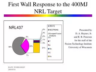
Filamentary heat load • Filaments in the far SOL are a small contribution to the ELM energy balance. • They are no problem at the divertor target. • But the parallel heat flow is up to 100 MW/m2 in AUG. • Requires tilted structures at the inner wall. • Extrapolation to ITER. Eich, T., et al., Physical Review Letters, 2003. 91(19). Eich, T., et al., Plasma Physics Controlled Fusion, 2005. 47 ITPA - Toronto - 2006
A. Kirk et al, PPCF 47 (2005) 315–333 Filament evolution in the pedestal region Hot filament near to the separatrix. Radial travveling into the far SOL, attached to the divertor. 3 ELM phases - diagnostics • Thomson scattering • Magnetic probes • Langmuir probesThermography • Li-beam • … ITPA - Toronto - 2006
Outline • Combined measurement of heat and particle flux in the mid-plane • ELM structure and correlations • Wall impact – e-folding lengths • Particle flux and heat load • Qualitative explanation • Filament expansion – Prediction and experiment • Summary ITPA - Toronto - 2006
Diagnostics • Combined measurements • Langmuir probes • Reciprocating • Filament probe • Thermography • Magnetic pick up coils • Probes are toroidal connected along field lines. • Outside the shadow of the protection limiter. • RP 5 mm in front of the ICRH limiter (connection length into the divertor about 5 m). ITPA - Toronto - 2006
Discharge scenario for radial SOL scan • Move the probes in front of the limiter. • Move the plasma away from the Limiter. • Radial scan 3.5 -12 cm • Discharge parameters • Ip= 0.8; 1.0 MA • Bt = -2; -3 T • n/ngw = 0.6 • Wmhd = const (500 kJ) • Pheat = 5; 6.6 MW NI • q95 = 3.5-6.5 ITPA - Toronto - 2006
Magnetic configuration • Field line connection to the divertor entrance. • No effectd from the 2nd X-point • Inner divertor -> heat shield • But, large gap. ITPA - Toronto - 2006
Correlation between signals • Filaments are seen on all probes (Langmuir pins, heat flux, magnetic) • Magnetic activity strongest at the beginning of an ELM. • jsat signals are correlated on a short spatial scale (Mach probe). • Parallel mass flow towards the outer lower divertor (M ab. 0.1). • Single filaments are detected as heat load: ITPA - Toronto - 2006
Heat load to the probe head is non-uniform 6 cm Leading edge • Rotation in co-current direction • ‘Sharp’ edge in the limiter shadow texposure = 2 μs Tframe = 100 μs ITPA - Toronto - 2006
Radial decay in the far SOL • Decay of maximum values. • Langmuir probes and heat flux have the same e-folding lengths! • Filament probe is about one radial e-folding length behind the reciprocating probe. For this plot: ITPA - Toronto - 2006
Radial decay is independent on the strength of the filament • The radial decay is independent on the strength of the filament. (Statistics, we do not follow a single filament) • Scatter due to different source strength or different radial velocity (less time for parallel convection) • Both Langmuir probes have comparable decay lengths. • Larger scatter for heat flux decay. • Heat flux decay is comparable (or larger) than the particle flux decay (jsat) ITPA - Toronto - 2006
Heat flux and ELM energy balance • The e-folding length is dominated by the density decay (Te, Ti = const) Qualitative explanation • We are measuring in the far SOL (away from the steep gradient near to the separatrix) • The electrons have lost their energy (modeling, experiment). • Loosing particles (and energy) without altering the temperature. Convective losses but collisional far SOL. ITPA - Toronto - 2006
Heat loss channels • n = 2e19m-3 • Te = 0.1 Ti Heat conduction (Kaufmann S 112, Stangeby S 394) electrons ITER Ions (D) ~n Heat convection (ions) ITPA - Toronto - 2006
Collisional SOL • Collisional edge • No significant heat exchange between electron and ions ; electron collision time (Wesson 2.15.3) ; ion collison time ; energy exchange time ITPA - Toronto - 2006
The ion temperature is below 100 eV • This is consistent with • Te < Ti : Heat load is dominated by ions: • Experimentally: ITPA - Toronto - 2006
Radial blob velocity S.I. Krasheninikov, PL A 283 (2001) 368 • Filament in contact with the wall – sheath resistivity • Far from the X-point. Blob velocity Blob / background density Ion gyro ratio/ poloidal size • Larger filaments are slower. • Faster with increasing density. ITPA - Toronto - 2006
Radial blob velocity • From experiment: • Poloidal size of 1-2 cm • Ion temperature <100 eV • Qualitative agreement with prediction. • But: • Size dependence? ITPA - Toronto - 2006
Summary and conclusions • The heat and particle decay length is a few centimeters in the far SOL • Particle and heat flux decay length are comparable. • The decay is dominated by ion-convection (energy and particles). • With a low Mach number (midplane, flow towards the lower divertor). • The ion temperature in the filament is below 100 eV. • The radial velocity from experiment and model is in agreement. • The fraction of ELM energy to the wall decreases with ELM size ITPA - Toronto - 2006