Download
1 / 13
130 likes | 240 Views
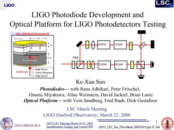
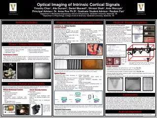
Analysis of the LIGO IFO Optical Control Signals. Evan Goetz University of Washington. Mentors: Dick Gustafson Rick Savage Paul Schwinberg. Overview. Pound-Drever-Hall Locking Monitoring Recycling cavity sidebands Project Goals Current Work What’s Next.

E N D
Analysis of the LIGO IFO Optical Control Signals Evan Goetz University of Washington Mentors: Dick Gustafson Rick Savage Paul Schwinberg
Overview • Pound-Drever-Hall Locking • Monitoring Recycling cavity sidebands • Project Goals • Current Work • What’s Next
Pound-Drever-Hall Locking • Length sensing system used in LIGO • Phase modulation of carrier SB • By monitoring SB signals we determine whether if the FP cavity is too large or small • The signal is used to drive cavity length errors to zero
Complications • We want to dynamically measure the power of each sideband • Presently, we monitor the 2f signal, SB+ x SB- = NSPOB • Higher sidebands also contribute (sum) at 2f: • SB2+ x C • SB2- x C • Etc. • We want to monitor uniquely SB+ and SB-
Gustafson-Goetz Technique • Mix IFO asymmetric port light with a shifted optical carrier signal (LO) to give unique RF signals for LO x SB+, SB-, C, etc. • Utilizing this technique, we will observe a unique RF frequency for each optical sideband Optical RF
Project Goals—Optical Table • Shift an optical carrier beam with AOM (LO) • Beat LO with original carrier + SB on a photodiode to detect our signal. • Evaluate how well this works on the optical table
Gustafson-Goetz Technique Test Schematic PM Pockels cell FP Cavity NPRO laser l/4 1 micron = 3e14 Hz Optical 30 MHz Carrier: 3e14 Hz + Sidebands AOM 80 MHz Photodiode RF Analyzer RF LO = Shifted carrier: 3e14 Hz + 80 MHz
Project Goals—IFO testing • Using fiber, transport the frequency shifted beam (LO) to the asymmetric port of the IFO and beat with output light • With a broadband PD, analyze the RF power products in real-time with the RF analyzer • Do IFO studies! • Devise a dedicated demodulator or receiver for each frequency
Extra Credit? Produce operational system for LHO’s IFOs
Current Work • Spending time getting familiar with the optics and electronics involved • Reading background literature on gravity-wave interferometry and PDH locking • Setting up optics and first testing on optical table
Implementation for LIGO IFO Mode cleaner PSL EOM AOM Fiber Coupling 100 m fiber Mode matching Photodiode RF Analyzer or dedicated electronics
What’s Next • Beat carrier + SB with LO on a PD • Work on free-space fiber coupling • Analyze RF products as seen by broadband PD • Implement and test on 2k or 4k IFO