Download
1 / 14
510 likes | 1.3k Views
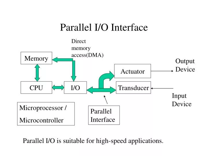
Parallel I/O Interface. Direct memory access(DMA). Memory. Output Device. Actuator. CPU. I/O. Transducer. Input Device. Microprocessor / Microcontroller. Parallel Interface. Parallel I/O is suitable for high-speed applications. General Structure of a parallel I/O Port.

E N D
Parallel I/O Interface Direct memory access(DMA) Memory Output Device Actuator CPU I/O Transducer Input Device Microprocessor / Microcontroller Parallel Interface Parallel I/O is suitable for high-speed applications.
General Structure of a parallel I/O Port Bidirectional data bus Chip Select Read/Write Clock Select Address lines Parallel I/O Port Tri-state I/O Lines Open-Collector I/O Lines Edge-Triggered Control Lines 1. Data I/O with tri-state output 2. Data I/O with open-collector output 3. Handshaking lines Standard Microprocessor Bus Interface
Bus Handshaking Protocols • Synchronous (Clocked transfer, one clock period per transfer) • Asynchronous (Unclocked, use handshake signals) • Semisynchronous (Clocked transfer, ome or more clock periods per transfer)
Synchronous Buses • The only control signal is a clock oscillator • Bus master: bus transmitter, put address on the bus • Bus slave: Bus receiver, respond to the master Setup, decode, and skew delay Clock Hold and Skew delay Address Data Write Read Write
Typical Slave Internal Structure Clock Data Address Address Decoder Bus Master Buffer Bus Slave
Timing Consideration • Bus lines must be stable before clock rises and after clock falls. • The following timing must be check for proper transaction • 1) Delay of address decoding • 2) Setup time and Hold time for logic • 3) Skew delay
Setup Time and Hold Time • Setup time is the minimum amount of time that a control signal has to be present on an input of memory device before the clock triggers a transfer into the device. • Hold time is the minimum time that data has to be held stable on the inputs of a memory device after a clock change triggers a transfer into that device.
Signal Skew A0 Sources of skew delay: 1) Differences in propagation delay 2) Varying logic gate delay 3) Rise time and Fall time 4) Gate threshold A1 D D The master transmits the signals over the bus to slave. The slave no longer sees the signals arrive at the same instant of time.
Advantage and Disadvantages of Synchronous Protocol • Advantage: Simplicity • Disadvantages:Problem with slow devices • Length of clock pulses Time needed for slave to response • So, slowest slave has to be considered. This reduces the bandwidth and decreases the potential system performance.
Asynchronous Buses • ComputerA mix of devices with widely varying access timesProblem of synchronous protocol: The bus runs at the speed of the slowest device. • Asynchronous buses allow: fast transactions for fast devices, slow transactions for slow devices.
Fully interlocked asynchronous bus Address Originating from bus master Master Slave Originating from bus slave Data Write Read Asynchronous bus handshaking
Asynchronous Buses • No timing relation to the system clock • Handshake lines are required (Fully interlocked protocol) • Matching the different speeds of external devices, fast transaction for fast device, slow transaction for slow device.
Semi-synchronous Buses • For fast devices: synchronous buses • Insert wait states using WAIT for slow devices. Clock Address Data Write Read WAIT
DMA and DMA Controller(DMAC) Microprocessor Memory DMA Controller I/O Port I/O Port I/O Port External Device External Device External Device