Download

1 / 52
560 likes | 1k Views
Field Hydraulics. For The Driver Operator. Hydraulics. Theory and application allowing control and use of fluid pressure. Hydraulic Theories.

E N D
Field Hydraulics For The Driver Operator
Hydraulics • Theory and application allowing control and use of fluid pressure
Hydraulic Theories • Understanding the theoretical and practical application of hydraulics essential for pump operation. The study of fire ground hydraulics is divided into two categories, theoretical and rule of thumb. The driver/operator must be able to apply both.
Elements of Hydraulic Calculation Nozzle Loss Attack Line Loss Elevation Loss Manifold/ Appliance Standpipe Loss Supply Line Loss
Terminology in Friction Loss Formulas • NP - Nozzle Pressure • FL - Friction Loss • AL - Appliance Loss • EL - Elevation Pressure • TPL - Total Pressure Loss • NPDP - Net Pump Discharge Pressure
Theoretical • In the classroom and non-emergency activities of the fire department, mathematical equations are used to calculate the flow characteristics of our equipment and systems. This method of calculation is commonly referred to as “Theoretical Hydraulics”. By using mathematical formulas, a relatively accurate calculation of the total probable friction loss is obtained. This method is normally more accurate than Rule of Thumb.
Theoretical Formula There are many formulas and methods for figuring friction loss but the Renton Fire Department has adopted the following for use in its training program. FL = CQ2L Where Q = Quantity C = Coefficient L = Length in 100’s
Hose Coefficients Coefficients for Renton Fire Department hose: 1 ¾ “ C = 15.5 2 ½ “ C = 2 3 ½ “ C = 0.34 5 “ C = 0.08
Siamesed Hose Lines Coefficients Two 2 ½” 0.5 Three 2 ½” 0.22
Rule of Thumb • On the fire ground, the driver/operator normally works with a condensed and simplified application known as “Rule of Thumb Hydraulics”. Rule of thumb hydraulic formulas are a chosen series of fixed, rounded values that can be applied to an operation sequentially to build a water delivery system.
Rule of Thumb Fixed Rounded Value Examples 2 ½” Combination Nozzle 250 GPM 1 ¾” Combination Nozzle 125 GPM 1 ¾” Hose 25 psi FL / Section 2 ½” Hose 06 psi FL / Section Master Stream Devices 25 psi FL Appliances (Wye etc…) 0 FL @ <350 gpm Appliances (Wye etc…) 10 psi FL @ > 350 gpm Elevation 05 psi FL / Floor
Appliance Pressure Loss < 350 gpm no calculated loss > 350 gpm 10 psi per appliance 25 psi for all master stream devices 25 psi for all standpipes
Nozzles and Tips Types of Nozzles Broken Stream Solid Stream Periphery Deflected (Combination ) Impinging stream(Naval type)
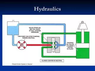
Nozzle Design The purpose of any nozzle is to provide a restriction of the flow to build pressure. This restriction, and subsequent created pressure, provides a usable velocity to project the water stream. For any one flow, there is one correct nozzle size (restriction) to develop the optimum pressure and velocity. Restriction
Pump Pressure Pump Pressure Designed Nozzle Pressure Smooth Bore Nozzle - Hand line - 50 PSI ½” thru 1 ¼” nozzles Smooth Bore Nozzle - Master Stream - 80 PSI nozzles 1 ¼” and over Fog Nozzle - 100 PSI all nozzles
Solid Stream - Characteristics The mechanical characteristics of a solid stream nozzle produce a compact stream that has a higher mass and velocity. These features typically yield better reach and penetration.
Solid Stream - Composition The interior diameter of the nozzle is gradually decreased until it reaches a point just short of the outlet. At this point the straight cylindrical bore has a length from 1 to 1 ½ times its bore, this area is known as the stream shaper
Solid Stream Mechanics Water flowing through a nozzle is subject to the same physical principals of friction as hose. The net effect of friction in a solid stream nozzle is the creation of a laminar flow. The center of the flowing stream is faster than the edge. This creates a peripheral turbulence that is visible after the stream exits the nozzle.
Solid Stream - Formulas • Discharge Volume: • 29.7 x D2 x NP • Nozzle Reaction: • 1.57 x D2 x NP
Fog Stream - Characteristics A stream of water remains in a solid mass, not losing continuity until it strikes an object, is overcome by gravity or is changed by friction with the air. Fog stream nozzles are designed around this theory and are commonly called broken stream appliances
Fog Stream - Composition All fog streams are of two mechanical types, Periphery-deflected or impinging stream. The shape and reach of a fog stream are results of the appliance shape and the velocity/pressure of the water.
Impinging Stream Impinging Stream fog patterns are produced by driving jets of water together at a set angle to break the streams into finely divided particles. These appliances generally produce wide angle fog patterns.
Periphery-Deflected Periphery –Deflected streams are produced by deflecting water from the periphery of an inside circular stem to the inner circumference of the adjustable barrel. The position of the barrel varies the shape of the stream from a light fog to a straight stream. There are two common types of these nozzles, automatic and non-automatic.
Periphery-Deflected, Automatic Automatic Periphery-Deflected nozzles have a spring loaded baffle assembly that reacts to incoming pressure. The baffle is calibrated to function at 100 PSI. The model illustrated has a sliding valve which allow the firefighter to meter the flow at the nozzle.
Periphery-Deflected, Automatic When pressure at the nozzle is less, the baffle moves in to maintain the pattern. When the pressure is greater than 100 PSI the baffle moves out to allow more volume and minimize the nozzle reaction.
Periphery-Deflected, Automatic Task Force Tip nozzles have a slide valve assembly that allows the water flow at the tip to be metered. By using this valve design, the nozzle has a smoother flow and less turbulence. Note the valve position in the illustrations.
Fog Stream - Formulas • Nozzle Reaction: • 0.0505 x Qx NP
Slide Valve Operation Slide Valve Gated ½ Way
Ball Valve Operation Ball Valve Gated ½ Way
Nozzle Reaction Nozzle reaction is the force that a firefighter feels when he is operating a nozzle. Nozzle reaction is primarily a result of discharge pressure at the nozzle. If the nozzle pressure is lowered, the firefighter will note a corresponding decrease in the nozzle reaction.
Nozzle ReactionTo calculate the nozzle reaction use the following formulas, note same flows can often be developed at a far lower nozzle reaction in solid stream nozzles. Traditional thought is that solid bore hand lines should be pumped at 50 psi. Any nozzle pressures higher than 65 psi becomes unmanageable. In the following table review and compare the reaction force of various fire streams. • Nozzle Reaction: Fog Stream • 0.0505 x Qx NP Nozzle Reaction: Solid Stream • 1.57 x D2 x NP
Handline Nozzle Reaction Chart 125 GPM 3/4” tip @ 56 NP = 49 NR combination @ 100 NP = 63 NR 150 GPM 7/8” tip @ 44 NP = 53 NR combination @ 100 NP = 76 NR 175 GPM 7/8” tip @ 60 NP = 72 NR combination @ 100 NP = 88 NR 200 GPM 1” tip @ 46 NP = 72 NR combination @ 75 NP = 87 NR combination @ 100 NP = 101 NR 250 GPM 1” tip @ 72 NP = 113 NR 1-1/8” tip @ 50 NP = 99 NR combination @ 100 NP = 126 NR 300 GPM 1” tip @ 100 NP = 157 NR 1-1/8” @ 64 NP = 127 NR combination @ 100 NP = 152 NR 325 GPM 1” tip @ 120 NP = 188 NR 1-1/8” tip @ 75 NP = 149 NR 1-1/4” tip @ 50 NP = 123 NR combination @ 100 NP = 164 NR
Theoretical Formula FL = CQ2L Where Q = Quantity C = Coefficient L = Length in 100’s
Hose Coefficients Coefficients for Renton Fire Department hose: 1 ¾ “ C = 15.5 2 ½ “ C = 2 3 ½ “ C = 0.34 5 “ C = 0.08
Siamesed Hose Lines Coefficients Two 2 ½” 0.5 Three 2 ½” 0.22
125 gpm 125 gpm 2 ½” – 400 ‘ 1 ¾” – 150’ 1 ¾” – 200’
Answer 100 psi NP 48 psi FL 1 ¾”, 200’ 50 psi FL 2 ½”, 400’ 198 psi NPDP (36 psi FL 1 ¾”, 150’ plus 5 psi elevation is less than 200’. Pump to the highest friction loss)
200 gpm 250 gpm 200’ of 5” 200’ 1 ¾” 200’ 2 ½”
Answer 100 psi NP 5 psi elevation 124 psi 1 ¾”, 200’ 10 psi appliance loss (>350gpm) 3.24 psi 5”, 200’ 242.24 psi NPDP (2 ½” FL is 25 psi, pump to the highest loss)
600 GPM 2 ea. 2 ½” 50’ 1 ½” tip 200’ of 5” 2 ½” 200’ 250 GPM
Answer 100 psi NP 25 psi FL, 2 ½” 10 psi AL 11.56 psi FL 5” 146.56 psi NPDP (NP 80 psi, 1 ½” tip 600 gpm / 25 psi FL Masterstream / 9 psi FL 2 ½” Siamese = 114 psi. Pump to the highest loss. Gate down the Master stream if necessary)
1 ¼” Solid Bore 1 ¾” 150’ 200 gpm 250’ 2 ½’ 125 gpm 2 ½’” 200’ 250 gpm 1 ¾” 200’
Answer 2 ½” 25 psi FL 100 psi NP 1 ¾” 200 gpm, 93 psi FL 1 ¾” 125 gpm, 48.4 psi FL 50 psi 2 ½” with 1 ¼” 328 gpm, 53.7 psi 193 psi NPDP, pump to the highest friction loss
150 gpm 40’ 200’ 1 ¾”
Answer 100 psi NP 17.36 psi EL (.434/ft) 69.75 psi FL 187.11 psi NPDP
200’ 1 ¾” 150 gpm 100” Siamesed 2 ½”
Answer 100 psi NP @ 150 gpm 69.75 psi FL 1 ¾”, 200’ 34.72 psi EL (.434 psi X 8 floors above the 1st) 25 psi FL Standpipe 01.125 psi FL Siamesed 2 ½” 230.59 psi NPDP
200’ of 1 ¾” @ 200 gpm 100’ of 2 ½”
Answer 100 psi NP @ 150 gpm 124 psi FL 1 ¾”, 200’ 34.72 psi EL (.434 psi X 8 floors above the 1st) 25 psi FL Standpipe 08 psi FL Siamesed 2 ½” 291.72 psi NPDP What single adjustment could you make to cut the friction loss by NPDP by 25 psi?