Download
1 / 50
560 likes | 853 Views
Chapter 4 Electromagnetic Propagation in Anisotropic Media Lecture 1 Light propagation in anisotropic media. Introduction :

E N D
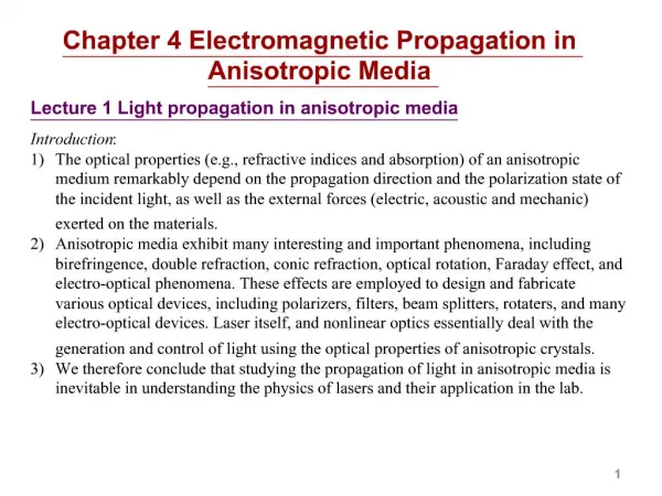
Chapter 4 Electromagnetic Propagation in Anisotropic Media Lecture 1 Light propagation in anisotropic media Introduction: • The optical properties (e.g., refractive indices and absorption) of an anisotropic medium remarkably depend on the propagation direction and the polarization state of the incident light, as well as the external forces (electric, acoustic and mechanic) exerted on the materials. • Anisotropic media exhibit many interesting and important phenomena, including birefringence, double refraction, conic refraction, optical rotation, Faraday effect, and electro-optical phenomena. These effects are employed to design and fabricate various optical devices, including polarizers, filters, beam splitters, rotaters, and many electro-optical devices. A significant portion of laser technology, and nonlinear optics deal with the generation and control of light using the optical properties of anisotropic crystals. • We therefore conclude that studying the propagation of light in anisotropic media is inevitable in understanding the physics of lasers and their application in the lab.
4.1 The dielectric tensor of an anisotropic medium Crystals are made up of regular periodical arrays of molecules. In an anisotropic crystal, the polarization induced by an electric field is in general not in the electric field direction. This can be seen if we consider that the electrons are anisotropically bonded in the crystal. • We currently make the following assumptions on the media: • Homogeneous. The medium is identical if translated internally. • Nonabsorption. e is real. Complex permittivity tensors will be considered later when we study the optical activity of crystals. • Linear. e does not depend on the strength of the external electric field. Nonlinear polarization is the basis of nonlinear optics, which we learn only a little in this course. • Nonmagnetic. m = m0. Our results can be easily extended to magnetically isotropic media.
The dielectric tensor eij is symmetric in a nonabsorption medium. This is an intrinsic symmetry. It comes from the nature of the thermodynamic requirement that Ueisa state function of E, which takes all Ei as independent variables. This does not require the symmetry of the crystal, or the linearity of the response.This can be generalized as follows. The real and symmetric dielectric tensor eij can then be diagonalized in the principle dielectric axis system: Relative permittivity
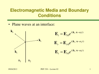
4.2 Plane wave propagation in anisotropic media In an anisotropic medium, the phase velocity of light depends on its polarization state and its propagation direction. For a given propagation direction, there exist in general two eigenwaves, each has its own eigen refractive index (or equivalently eigen phase velocity )and eigen polarization. All light traveling in that direction can be decomposed onto the two eigenwaves. Question: For a given wave normal directions in the crystal, what are the eigen refractive indices and eigen polarizations?This is answered by solving the Maxwell’s equations with an anisotropic dielectric tensor. Suppose the phase of all the electromagnetic fields (E, H, D, and B) varies in the form: E D a k (s) a H (B) S=E×H (t) Relations between the directions of the vectors: • D, H, and s are mutually perpendicular. • D, E, s,and E×H (energy flow) lie in the same plane. • The Poynting vector S=E×H is generally not along s.
Wave normal direction s and energy transfer direction t E D a k (s) a H (B) S=E×H (t)
Lecture 2 Eigenwave equation We continue to search for the eigenwaves propagating along a given direction in a crystal. This is the eigenwave equation for determining the eigen refractive indices (eigen values) and polarization (eigen states) of a plane wave propagating in a prescribed direction s. We now realize it in the matrix form. Fun math tricks:
Solving the eigenwave equation:For a nontrivial solution of E, the determinant of the matrix must be 0.
One easier way to solve the eigenwave equationis given below: • Question: For a given wave normal direction s in the crystal, what are the eigen refractive indices and eigen polarizations? • Answer: • In general two refractive indices, n1 and n2, are given by solving the Fresnel’s equation of wave normals. • The polarization direction of E of each eigen state is given by
4.4 Phase velocity, group velocity, and energy velocity The phase velocity of a plane wave is Therefore in general each of the two eigenwaves in a crystal has its own phase velocity. Group velocity isthe velocity of energy flow of a laser pulse in a dispersive medium.We now generalize the concept of group velocity, where the light pulse moves in a bundle of directions centered at k0. We decompose the light in the k-space (momentum space). In k-space, w(k) = const is called a wave normal surface. Group velocity is the gradient of the wave normal surface in k-space, and is therefore always perpendicular to the wave normal surface.
The energy velocity is defined as For a non-absorptive medium, vg= ve. A neat proof is given in our textbook. group velocity kz w(k) = const normal surface k-space ky kx
Lecture 3 Wave normal surface in the k-space We now express the Fresnel’s equation of wave normals in terms of k=(kx, ky, kz), that is, in the k-space. This is not mathematically new compared to what we have done by using n and s to express k. However, the k-space gives us more convenience.
This determinate can be simplified into This is an w(k) = constant wavenormal surface.The surface is composed by all the wave normals k that have the same frequency w.Note that the relative permittivities also depends on frequency. For future use, we simplify the equation for some special cases.
Wave normal surface in the k-space: • The wave normal surface w(k) = w =constant contains the end points of all the k vectors for a given frequency w. Here are the general characteristics of the wave normal surface. • The wave normal surface consists of two shells, with only four points in common. • The two lines that go through the origin and the four common points are called the optic axes. When light is propagating in the direction of one of the two optic axes, there is only one possible k value, and thus only one refractive index. • Any other light propagating direction intersects the two shells of the wave normal surface at two different points, giving two possible k values, and thus two refractive indices for the two eigenwaves. • For each eigenwave, the energy flow (group velocity or energy velocity) of the light is perpendicular to the wave normal surface at its k point. • Once wave vector k is known, the polarization of the corresponding E field of the eigenwave is given by
Spatial relations between the fields of the two eigenwaves: E1 D1 a S2(t2) b k (s) H1(B1) a b D2 S1(t1) E2 H2(B2) Orthogonality of the two eigenwaves:
Lecture 4 The index ellipsoid 4.3 The index ellipsoid When light propagates in a crystal, the D vectors of the two eigenwaves and the wave normal direction s form a mutually perpendicular triad. It is therefore more convenient to present the field vectors in the D space. The electric energy density Ue is given by The constant energy density surface in D space is then If we denote then we have This surface is called the index ellipsoid(or the optical indicatrix).
The role of the index ellipsoid: • For a given arbitrary wave normal direction s, the index ellipsoid can be used to • Find the indices of refraction of the two eigenwaves. • Find the corresponding directions of the D vectors of the two eigen waves. • The prescription is as follows: • Draw a plane that is through the origin and is perpendicular to s. This plane intersects the index ellipsoid surface with a particular intersection ellipse. • The lengths of the two semiaxes of the intersection ellipse, n1 and n2, are the two indices of refraction of the eigenwaves. • The two axes of the intersection ellipse are each parallel to the D vectors of the eigenwaves. s D2 n2 n1 D1
Proof of the prescription of using the index ellipsoid: The intersection ellipse is given by The lengths (squared) of the semiaxes of the ellipse is given by the extrema of subject to the above two auxiliary conditions. This can be solved by the Lagrange undetermined multipliers method, construct The extrema of is then given by solving
That is, if we assume the extrema of the intersection ellipse be , then the resultant E fields will be on the right polarizations, and the resultant n1 and n2 will satisfy the Fresnel’s equation of wave normals.
Comparison of the wave normal surface method and the index ellipsoid method • We have studied the wave normal surface method and the index ellipsoid method on light propagating in anisotropic crystals. Let us compare them here. • The wave normal surface shows us the allowed two wave vectors, and thus the refractive indices, at a given light propagation direction. The index ellipsoid does similar things, plus it also shows us the allowed direction of the D vectors. • The index ellipsoid displays the refractive indices and the directions of the D vectors in a convenient visual way. It also involves easier mathematics. Because of this simplicity, it is often first considered in solving problems. • However, the knowledge in the wave normal surface is much more profound. For example, it displays the optic axes. It shows the wave vector variation in the k-space. It shows the energy transfer direction. It has more mathematical base, and therefore allows for deeper theoretical derivations. • We tentatively summarize that for solving problems of light propagating in anisotropic crystals, we may first try the index ellipsoid method. However, we need to keep in mind that we have a backup more powerful wave normal surface method. This is especially true when we are directly dealing with the wave vectors rather than merely the refractive indices in the problems.
Lecture 5 Light propagation in uniaxial crystals 4.5 Classification of anisotropic media (crystals) Crystals are optically classified into 3 groups, namely the isotropic (or cubic) , the uniaxial, and the biaxial crystals, according to the number of independent elements of their dielectric tensors in the principle axis systems. Our text shows many examples of isotropic and anisotropic crystals commonly used in making optical devices.
4.6 Light propagation in uniaxial crystals The index ellipsoid: The equation of the index ellipsoid of a uniaxial crystal is z s De q ne (q) y no Do The index ellipsoid is rotationally symmetric around the z-axis. Let s be in the y-z plane with a polar angle q. The two polarization directions of the D vectorsare: Dois parallel to the x-axis, Deis in the y-z plane and is perpendicular to s. The corresponding refractive indices are: When s is on the z direction, ne(0°) = no. Therefore the z-axis is the optic axis.
The wave normal surface: s De(q) ne (q) q no no ne Do The refractive indices are given by solving the two factors: Positive uniaxial crystal s De(q) no q Notes to uniaxial crystals: At a given propagation direction, there are in general two eigen refractive indices, each has its own eigen polarization direction. This is called birefringence. The E field of the o-ray is always polarized perpendicular to the plane that contains s and the optic axis, while the e-ray is polarized parallel to that plane. ne (q) no ne Do Negative uniaxial crystal
Lecture 6 Double refraction • 4.7 Double refraction at a boundary • Up to now we discussed the light propagation in an anisotropic crystal when it is already inside the crystal, but how is the light refracted into the crystal? • We recall that the boundary condition requires • The wave vectors of the incident, reflected, and refracted light ( ) lie in the plane of incidence. • The tangential components of all three wave vectors on the boundary interface is the same: • We know that in the crystal the length of kt depends on the angle of refraction qt , as well as the orientation of the optic axes. Each qt supports two kt because of the double shell structure of the wave normal surface. k0 q0 boundary q2 k1 k2 Also because of the double shell structure of the wave normal surface, in general there are two refraction angles, q1andq2, both satisfy q1 wave normal surfaces
The refraction at a boundary can be explained on the intersection between the wave normal surface and the plane of incidence. At the boundary, the k0 beam is uniquely decomposed into the reflected beam and the two eigenstates of the refracted k1 and k2 beams, according to the boundary conditions. Each refracted beam then propagates separately. This is called double refraction. Please note that in general the polarization of the k1 and k2 beams are not orthogonal since they are in different directions. The incident light still can be uniquely decomposed into the reflected beam and the two refracted beams according to the boundary conditions. k0 q0 boundary q2 k1 k2 Internal double reflection: When light is internally reflected from the surface of an anisotropic material, double reflection may occur. It can be discussed similarly on the intersection between the wave normal surface and the plane of incidence. q1 wave normal surfaces
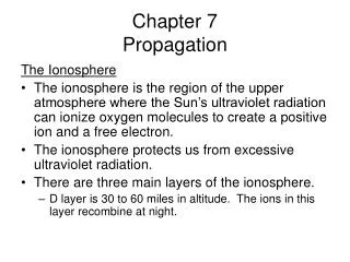
Double refraction at the boundary of a uniaxial crystal: Examples The directions of the D vectors are shown. There exist an ordinary wave with the refractive index no, and an extraordinary wave whose refractive index ne depends on its direction of propagation. optic axis ki optic axis optic axis ki ki Positive uniaxial crystal ko ke ko ko ke ke optic axis optic axis optic axis ki ki ki Negative uniaxial crystal ke ke ke ko ko ko
e o
Deviation angle between the energy flow of the o-ray and e-rays Suppose the light is incident normally on the surface of a uniaxial crystal. Then the wave vectors koand ke are in the same direction. Let us see how much the energy flow of the e-ray is deviated away from that of the o-ray. z te s (to) a b De ne (q) q Ee y no Do(Eo) Example: For KDP (KH2PO4) crystal, no=1.50737, ne=1.46685. At q =45°, the angle between the e-ray and the o-ray is a =1.56°.
Lecture 7 Light propagation in biaxial crystals z 4.8 Light propagation in biaxial crystals The index ellipsoid:The equation of the index ellipsoid of a biaxial crystal is s n(b)=ny b D2 x ny D1 Generally for a wave normal direction s (q,j) there exist two allowed vectors D1 and D2 with their specific refractive indices n1 (q,j) and n2 (q,j). If s is in the x-z plane, we have n1(q)= ny always, and n x<n2 (q)< nz. Since n x<ny< nz, there exists a special angle b which makes n2 (b)= n1 (b)= ny. That is, the intersection ellipse is a circle and there is no difference between the two refractive indices. This special direction b is called the optic axisof the crystal.For a biaxial crystal, there are two such optic axes, both are on the x-z plane. They are located symmetrically on each side of the z-axis. Thus comes the name biaxial crystal. It is not difficult to find that the polar angle of the two optic axes is given by
When an unpolarized light is propagating along the optic axis of a biaxial crystal, the allowed D vector is in any direction perpendicular to the s vector. This results in the allowed E vectors locating in one plane. The ray direction t is then found to form a cone on one side of the light propagation direction s. Any plane perpendicular to s intersects the cone with a circle. This phenomenon is called conical refraction. Conical refraction is predicted by William Hamilton in 1832, and was confirmed experimentally by Humphrey Lloyd the next year. Both were Irish scientists. We discuss the details of conical refraction later using the wave normal surfaces. t1 s t2 D1 t3 E1 D2 y E2 E3(D3)
Wave normal surfaces: We already know that the wave normal surface of a biaxial crystal consists of two complex shells, with only four points in common. Let us consider the intersections between the wave normal surface and the three coordinate planes. If we set ky=0, then This consists of a circle with the radius nyw/c, and an ellipse with semiaxes nzw/c and nxw/c. The intersections with the other two coordinates planes are similar, each has a circle and an ellipse. The optic axes lie in the x-z plane.
Lecture 8 Conical refraction Conical refraction: The group velocity of light is the gradient of the wave normal surface in the k-space, and is thus perpendicular to the wave normal surface. However, on the optic axis, the two shells of the wave normal surface degenerate into a point, which is a singular point where the gradient is not well defined. The energy flow of light at this point is governed by the nature of the singularity. We then need to examine the shape of the wave normal surface at that point. The wave vector at the singular point is given by k0 b
We are interested in the neighborhood of this singular point. We therefore do a Taylor expansion of the wave normal surface at this point. substitute it into the equation of the wave normal surface and keep up to the second power of x, y, and z, we have (I confirmed it by Mathematica.) This is a cone with its vertex at k0. The cone is symmetric about the y =0 plane. b
The cone intersects the y=0 plane by two lines, which make an angle 2c given by We then rotate the x-z axes by an angle of p/2−b +c to the x'-z' axes. The cone will be erect in the new coordinates ( I confirmed it by Mathematica): b The energy flow is everywhere perpendicular to this cone surface, which form a light cone of for conical refraction. k0
The light cone due to conical refraction • has the following characters: • The cone contains the optic axis as • All other lights on the cone are above the optic axis (if the z axis is upward). • The cone has an apex angle of 2c in the y'=0 plane. • The cone intersects any plane that is perpendicular to the optic axis with a circle. Proof of 4): We rotate x'-z' axes by an angle of –c to the x"-z" axes. The cone will be It is a circle at any x"=const. b k0
Lecture 9 Phase-matching in second harmonic generation Second harmonic generation When an intense laser beam passes through a crystal, the molecules of the crystal can be nonlinearly polarized, which causes the crystal radiate at the doubled frequency of the incident light. This is called second harmonic generation. Suppose the incident light has a frequency of w. It passes through a crystal with thickness L in the x direction. Suppose the E-field of the incident light (which is called the fundamental beam) is We suppose the conversion to second harmonic is small so that the amplitude of the fundamental beam is almost constant. We take care of the polarization issue later. The second order nonlinear polarization of the material is Here c(2) is the second order nonlinear optical susceptibility. According to the theory of radiation, the complex field for the second harmonic that is generated by the crystal inside dx but observed at L is Here a is just a constant. dx x L
The total field of the second harmonic at the output surface of the crystal is then is the phase mismatch. (I believe it should be called the wave-vector mismatch,and DkL should be called the phase mismatch. This mistake was made by somebody many years ago.) The intensity of the produced second harmonic is • For efficient second harmonic generation: • Conversion efficiency • Phase-matching conditionThis requirement is critical due to the narrow shape of the sinc function.
Phase-matching in BBO crystal BBO (Beta-Barium Borate, β-BaB2O4) is a negative uniaxial optical crystal, i.e., ne< no. The index ellipsoid is with the z-axis as the optic axis. Let q be the direction of the light wave, the refractive index of the e light, ne(w, q), is then Phase-matching condition requires that . This is impossible if both the fundamental and the second harmonic are o-rays, or both are e-rays, because of the dispersion of the material. However, since ne< no, and normally , we can let w be o-ray and 2w be e-ray, and hopefully to accomplish the phase-matching condition. That is o + o e, which is called type-I phase-matching. For contrast, type-II phase matching refers to o + e o or e.
To achieve type-I phase-matching in BBO, the phase-matching angleqm, where Dk=0, is given by This is not hard to calculate because we have the analytic Sellmeier equations for the refractive indices as a function of the wavelength or frequency. The Sellmeier equations of BBO are (l in mm): no2(l) = 2.7359+0.01878/(l 2-0.01822)-0.01354 l 2 ne2(l) = 2.3753+0.01224/(l2-0.01667)-0.01516 l2 We then find that the BBO crystal can achievethe phase-matching condition for inputwavelengths down to a little more than 400 nm. Phase-matching angle in BBO crystal
Angular sensitivity of phase-matching: 1.0 I (2w) 0.5 DkL 2.783 This is only 0.11°for a BBO crystal of 1-mm long with an input beam at 600 nm. Therefore the phase-matching condition is extremely angular-sensitive.In practice the experimental angular width of phase matching can be larger, because 1) The angle is measured outside the crystal. 2) The laser has a bandwidth. 3) Intensity saturation. 4) A Gaussian beam has a divergence in its propagation directions. Similarly we can also calculate the wavelength sensitivityfor phase-matching. It is found to be about 1 nm for 1-mm thick BBO crystal, which is again quite sensitive.
Angular and wavelength sensitivity of phase-matching in BBO crystal DkL=0 2Dq 2Dl DkL=±2.783
Lecture 10 Optical activity 4.9 Optical activity Optical activity refers to the phenomena that when a linearly polarized light is passing through a medium, the polarization plane is rotated. It is thus also called optical rotation. When this happens, the medium is said to be optically active. The rotation of the polarization plane is proportional to the path length of the light, and can be measured by degree/centimeter. Common optically active media include quartz, sugar and syrup. It can be used to measure blood sugar concentration in diabetic people. Optical activity occurs in a chiral molecule, where the molecule does not overlap with its mirror image, and the electron cloud takes some kind of helical shape. Left- and right-circularly polarized light is different in polarizing a chiral molecule, which causes different refractive indices. This is called circular birefringence (or circular double refraction). Most amino acids (the building blocks of life) are left-handed, which makes optical activity prominent in nature. If when observed facing the light the rotation of the polarization plane is counterclockwise, the substance is dextrorotatory (right-handed). When the rotation is clockwise, it is called levorotatory (left-handed).
Explaining optical activity using circular birefringence: Suppose light is linearly polarized on the x-axis, and is propagating along the z-axis. Suppose the refractive indices for circularly polarized light is nr and nl. The specific rotatory power is which is very sensitive in measuring circular birefringence.
Theory on optical activity: A helical molecule can be polarized along its axis by a circulating current driven by an circular electric field produced by a time-varying magnetic field: The constitutive equation of a medium driven by a plane wave is then revised to Gs=G is called the gyration vector. The length G of the gyration vector describes the rotation power of the medium. It varies with the direction of the wave, and can be expressed by a gyration tensor g of the medium as Now our original eigenwave equation is revised to After realizing it into the matrix form, we have
For a nontrivial solution of E, the determinant of the matrix must be 0, which is simplified to The corresponding wave normal surface is I believe this surface is formidable for anyone attempting to draw using Mathematica. Fortunately equation 1 can be simplified to , where n1 and n2 are the solutions of the equation with G=0, i.e., when there is no optical activity.On the optic axis, we have the eigen refractive indices are then These are two circularly polarize waves, with a rotary power of
The eigen polarization state in an optically active medium: If we solve equation 1 for the two general eigen refractive indices, and then substitute into the eigenwave equation, we may have the eigen polarization states for light in an optically active medium. Surely it is too complicated. Our textbook did it in a simple way. We can rewrite the eigenwave equation into that for the D vector, and express it in the (D1, D2, s) coordinate system, thus reducing one dimension. The corresponding eigen polarization, when G is small, and in terms of D, is D2 D1 • We conclude that • The eigen polarization states are generally two orthogonal elliptically polarized waves, oriented along the D1 and D2 axes. • In an isotropic medium, or when the light is propagating in the optic axis of an anisotropic medium, the eigen polarizations are left- and right- circularly polarized light. • In an anisotropic medium, and when the light is not close to the optic axis, because G is usually much smaller than , the light is almost linearly polarized.
k b B k B k B d 4.10 Faraday rotation Faraday rotation refers to the phenomena that when a linearly polarized light is passing through a medium placed in an external magnetic field, which is along the light propagation direction, the polarization plane is rotated.The origin of the effect is as follows. The electrons are moving in a molecule, driven by the electric field of the light. The external magnetic field will displace the electrons laterally due to the Lorentz force qv×B. The induced dipole momentum then includes a term proportional to E×B. The constitutive equation is then Here g is the megnetogyration coefficient, gB is the gyration vector. The discusses followed should be similar to optical activity, with a specific rotation given by , where V is called the Verdet constant, can be measured by deg/Gauss·mm. One distinct difference between optical activity and Faraday effect is the reversibility of the effect when the light is going back. Optical activity is reversible, while in Faraday effect when the light is reversed the rotation is doubled. This is ready to explain by the two constitutive equations:
Optical isolator: An optical isolator, or optical diode, is an optical device that allows the transmission of light in only one direction. It is used to prevent unwanted light feedback into a laser cavity. The operation of the device depends on the non-reversibility of Faraday effect. The optical isolator in the figure consists of three parts. An input polarizer allows only vertically polarized light to pass. A Faraday rotator rotates the polarization by 45°. An output polarizer (analyser) just let the 45° polarized light to pass by. If light is feed back from somewhere later in the path, the Faraday rotator will turn it into horizontally polarized light, which is then absorbed (or deflected) by the first polarizer.