Download
1 / 61
640 likes | 887 Views
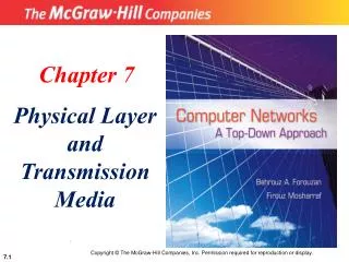
COE 341: Data & Computer Communications (T061) Dr. Radwan E. Abdel-Aal. Chapter 4: Transmission Media. Remaining five chapters:. Chapter 7: Data Link: Flow and Error control, Link management. Data Link. Chapter 8: Improved utilization: Multiplexing. Physical Layer.

E N D
COE 341: Data & Computer Communications (T061)Dr. Radwan E. Abdel-Aal Chapter 4: Transmission Media
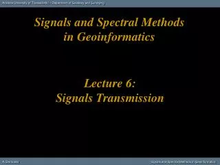
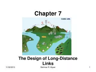
Remaining five chapters: Chapter 7: Data Link: Flow and Error control, Link management Data Link Chapter 8: Improved utilization: Multiplexing Physical Layer Chapter 6: Data Communication: Synchronization, Error detection and correction Chapter 4: Transmission Media Transmission Medium Chapter 5: Encoding: From data to signals Chapter 3: Signals, their representations, their transmission over media, Impairments
Agenda • Overview • Guided Transmission Media • Twisted Pair • Coaxial Cable • Optical Fiber • Unguided (open space, wireless) Transmission • Antennas • Terrestrial Microwave • Satellite Microwave • Broadcast Radio • Infrared
Overview • Media: • Guided - wire • Unguided - wireless • Transmission characteristics and quality determined by: • Signal • Medium • For guided, the medium is important • For unguided, the antenna is important
Design Issues • Key communication objectives are: • High data rate • Low error rate • Long distance • Bandwidth: Tradeoff - Larger for higher data rates - But smaller for low link cost • Transmission impairments • Attenuation: Twisted Pair > Cable > Fiber (best) • Interference and Cross talk: Twisted Pair > Cable > Fiber (best) Worse with unguided… (the medium is shared!) • Number of receivers • In multi-point links of guided media: Attenuation increases with increased number of connected receivers
Part of the Electromagnetic Spectrum f 1 KHz 1 MHz 1 GHz 1 THz Guided Unguided l V = l f
Study of Transmission Media • Physical description • Main transmission characteristics • Main applications
Guided Transmission Media • Twisted Pair • Coaxial cable • Optical fiber
Frequency Range Typical Attenuation Typical Delay Repeater Spacing Twisted pair (with loading) 0 to 3.5 kHz 0.2 dB/km @ 1 kHz 50 µs/km 2 km Twisted pairs (multi-pair cables) 0 to 1 MHz 3 dB/km @ 1 kHz 5 µs/km 2 km Coaxial cable 0 to 500 MHz 7 dB/km @ 10 MHz 4 µs/km 1 to 9 km Optical fiber 186 to 370 THz 0.2 to 0.5 dB/km 5 µs/km 40 km Transmission Characteristics of Guided Media: Overview
UTP Cables unshielded
Twisted Pair - Applications • The most commonly used guided medium • Telephone network (Analog Signaling) • Analog Data (original purpose) : Between houses and the local exchange, e.g. 5 km (subscriber loop) • Digital Data: Transmitted using modems, low data rates • Within buildings (short distances) (Digital Signaling) • To private branch exchange (PBX) (64 Kbps) • For local area networks (LAN) (10-100Mbps) Example, Ethernet: 10BaseT: Unshielded Twisted Pair, 10 Mbps,100m range
Twisted Pair - Pros and ConsCompared to other guided media Pros: • Low cost • Easy to work with (pull, terminate, etc.) Cons: • Limited bandwidth Limited data rate • Limited distance range (due to large attenuation) • Susceptible to interference and noise
Twisted Pair - Transmission Characteristics • Analog Transmission Mode • For analog signals only • Amplifiers every 5km to 6km • Bandwidth up to 1 MHz (several voice channels): ADSL (Ch 8) • Digital Transmission Mode • Using either analog or digital signals • Repeaters every 2km or 3km • Data rates up to few Mbps (1Gbps: over very short distances) • Impairments: • Attenuation: A strong function in frequency, can be modified with loading coils • EM Interference: Crosstalk, Impulse noise, Mains interference
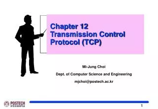
Attenuation in Twisted pairs (unloaded) Thinner Wires Wire Gauge Wire Diameter 1 MHz 300 1 KHz 3400 Telephone Voice
Ways to reduce EM interference • Shielding the TP with a metallic braid or sheathing • Twisting reduces low frequency interference Tighter twisting Better performance • Using different twisting lengths for adjacent pairs to reduce crosstalk
Unshielded (UTP) and Shielded (STP) • Unshielded Twisted Pair (UTP) • Ordinary telephone wire: Abundantly available in buildings • Cheapest • Easiest to install • Suffers from external EM interference • Shielded Twisted Pair (STP) • Shielded with metal braid or sheathing: • Reduces interference • Reduces attenuation at higher frequencies Better Performance: • Increases data rates used • Increases distances covered • But becomes: • More expensive • Harder to handle (thicker, heavier) Transmit faster and go further!
UTP Categories: EIA-568-A Standard (1995) (cabling of commercial buildings for data) • Cat 3 • Up to 16MHz • Voice grade • In most office buildings • Twist length: 7.5 cm to 10 cm • Cat 4 • Up to 20 MHz • Cat 5 • Up to 100MHz • Data grade • Pre-installed in many new office buildings • Twist length: 0.6 cm to 0.85 cm (Tighter twisting increases cost but improves performance)
Near End CrossTalk (NEXT) • Coupling of signal from a wire pair to an adjacent pair • Coupling takes place when a transmitted signal entering a pair couples (leaks) into an adjacent receiving pair on the same (near) end of the link Transmitted Power, P1 Disturbing pair Coupled Received Power, P2 Disturbed pair “NEXT” Attenuation = 10 log P1/P2 dBs The larger … the smaller the crosstalk (The better the performance) NEXT attenuation is a desirable attenuation- The larger the better!
Signal Attenuation (dB per 100 m) Near-end Crosstalk Attenuation (dB) Frequency (MHz) Category 3 UTP Category 5 UTP 150-ohm STP Category 3 UTP Category 5 UTP 150-ohm STP 1 2.6 2.0 1.1 41 62 68? 4 5.6 4.1 2.2 32 53 58 16 13.1 8.2 4.4 23 44 50.4 25 — 10.4 6.2 — 41 47.5 100 — 22.0 12.3 — 32 38.5 300 — — 21.4 — — 31.3 Transmission Properties for Shielded & Unshielded TP Undesirable Attenuation- Smaller is better Desirable Attenuation- Larger is better! Better Better Better Better Not Usable Not Usable
Category 3 Class C Category 5 Class D Category 5E Category 6 Class E Category 7 Class F Bandwidth 16 MHz 100 MHz 100 MHz 200 MHz 600 MHz Cable Type UTP UTP/FTP UTP/FTP UTP/FTP SSTP Link Cost (Cat 5 =1) 0.7 1 1.2 1.5 2.2 Newer Twisted Pair Categories and Classes UTP: Unshielded Twisted Pair FTP: Foil Twisted Pair SSTP: Shielded-Screen Twisted Pair
Coaxial Cable Physical Description: 1 - 2.5 cm Designed for operation over a wider frequency rage
Coaxial Cable Applications Frequency Division Multiplexing • Most versatile medium • Television distribution (FDM Broadband) • Cable TV (CATV): 100’s of TV channels over 10’s Kms • Long distance telephone transmission • Can carry 10s of thousands of voice channels simultaneously (though FDM multiplexing) (Broadband) • Now facing competition from optical fibers and terrestrial microwave links • Local area networks, e.g. Thickwire Ethernet cable (10Base5): 10 Mbps, Baseband signal, 500m segment
Coaxial Cable - Transmission CharacteristicsImprovements over TP • Extended frequency range • Up to 500 MHz • Reduced EM interference and crosstalk • Due to enclosed concentric construction • EM fields terminate within cable and do not stray out • Remaining limitations: • Attenuation • Thermal and noise • Inter modulation noise (especially for broadband operation) Because of FDM
Coaxial Cable - Transmission Characteristics • Analog Transmission • Amplifiers every few kms • Closer spacing for higher frequency • Digital Transmission • Repeater every 1km • Closer repeater spacing for higher data rates
Optical Fiber • A thin (2-125 mm) flexible strand of glass or plastic • Light entering at one end travels confined within the fiber until it leaves at the other end • As fiber bends around corners, the light stays within the fiber • Lowest losses (attenuation) with ultra pure fused silica glass… but difficult to manufacture • Reasonable losses and performance with multi-component glass and with plastic Cost, Difficulty of Handling Attenuation (Loss) Pure Glass Multi-component Glass Plastic Best Performance
Single Fiber Cable Optical Fiber: Construction • An optical fiber consists of three main parts • Core • A narrow cylindrical strand of glass/plastic, with refractive index n1 • Cladding • A tube surrounding each core, with refractive index n2 • The core must have a higher refractive index than the cladding to keep the light beam trapped inside: n1 > n2 • Protective outer jacket • Protects against moisture, abrasion, and crushing Individual Fibers: (Each having core & Cladding) Multiple Fiber Cable (Note multiple cladding)
Reflection and refraction of light • At a boundary between a denser (n1) and a rarer (n2) medium, n1 > n2 (e.g. water-air, optical fiber core-cladding) a ray of light will be refracted or reflected depending on the incidence angle Shallower Incidence Increasing Incidence angle, 1 2 rarer v2 = c/n2 n2 denser 2 1 n1 critical 1 n1 > n2 v1 = c/n1 Total internal reflection Critical angle refraction Refraction
Optical Fiber Refraction at boundary for . Escaping light is absorbed in jacket i < critical n2 Rarer Denser Denser n1 n1 Rarer i Total Internal Reflection at boundary for i > critical n1 > n2
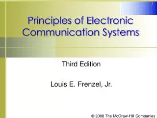
Which side is the IR? Attenuation in Guided Media Compare attenuation ranges!
Optical Fiber - Benefits • Greater channel capacities over larger distances • Fiber: 100’s of Gbps over 10’s of Kms • Cable: 100’s of Mbps over 1’s of Kms • Twisted pair: 100’s of Mbps over 10’s of meters • Lower/moreuniform attenuation (Fig. 4.3c) • An order of magnitude lower • Relatively constant over a larger frequency interval • Electromagnetic isolation • Fiber is not affected by external EM fields: • No interference, impulse noise, crosstalk • Fiber does not radiate (light ray trapped inside): • Not a source of interference • Difficult to tap (data security) But what could happen at the repeater?
Optical Fiber – Benefits, Contd. • Greater repeater spacing: Fewer Units, Lower cost • Fiber: 10-100’s of Kms • Cable, Twisted pair: 1’s Kms • Smaller size and weight: • An order of magnitude thinner for same channel capacity • Useful in cramped places • Reduced cost of digging in populated areas • Reduced cost of cable support structures
Optical Fiber - Applications • Long-haul trunks between cities • Telephone traffic over long routes between cities, and undersea: • Fiber & Microwave now replacing coaxial cable • 1500 km, Up to 60,000 voice channels • Metropolitan trunks • Joining exchanges inside large cities: • 12 km, Up to 100,000 voice channels • Rural exchange trunks • Joining exchanges of towns and villages: • 40-160 km, Up to 5,000 voice channels • Subscriber loops • Joining subscribers to exchange: • Fiber replacing TP, allowing all types of traffic • LANs, Example: 10BaseF 10 Mbps, 2000 meter segment Exchange City City Competition: Fiber, Coaxial, m Waves Main Exchange Compare segment length with twisted pair and coaxial!
Optical Fiber - Transmission Characteristics • Acts as a wave guide for light (1014 to 1015 Hz) • Covers portions of infrared and visible spectrum • Transmission Modes: Multimode Single Mode Single ray Graded Index Step Index Multiple rays
i < critical n2 n1 Dispersion: Spread in ray arrival time Optical Fiber Transmission Modes Refraction Shallow reflection Deep reflection n2 n1 Large Core n1 > n2 Cladding 2 ways to reduce dispersion: Smaller • v = c/n • Make n1 lower away from center…this speeds up deeper rays • and compensates for their larger distances, arrive together with shallower rays Smallest
Optical Fiber – Transmission modes • Spread of received light pulse in time (dispersion) is bad: • Causes inter-symbol interference bit errors • Limits usable data rate and usable distance • Caused by propagation through multiple reflections at different angles of incidence • Dispersion increases with: • Larger distance traveled • Thicker fibers with step index • Dispersion can be reduced by: • Limiting the distance • Thinner fibers and a highly focused light source In the limit: Single mode: High data rates, very long distances • Graded-index thicker fibers: The half-way solution
The transmission system is not just the medium (fiber)! We have also light Sources and detectors… Light Sources • Light Emitting Diode (LED) • Lower cost, longer life • Wider operating temp range • Injection Laser Diode (ILD) • More efficient (more light power for same electric power input) • Faster switching Higher data rate
Wavelength Division Multiplexing (WDM) • A form of FDM (Channels sharing the medium by occupying different frequency bands) • Multiple light beams at different frequencies (wavelengths) transmitted on the same fiber • Each beam forms a separate communication channel • Example: 256 channels @ 40 Gbps each 10 Tbps total data rate
Optical Fiber – Four Transmission bands (windows) in the Infrared (IR) region • Selection based on: • Attenuation of the fiber • Properties of the light sources • Properties of the light receivers S L C Bandwidth, THz 33 12 4 7 Note: l in fiber = v/f = (c/n)/f = (c/f)/n = l in vacuum / n i.e. l in fiber < l in vacuum l values shown are in vacuum
Wireless Transmission • Free-space is the transmission medium • Need efficient radiators, called antennas / aerials • Signal fed from transmission line (wireline) and radiated into free-space (wireless) • Popular applications • Radio & TV broadcast • Cellular Communications • Microwave Links • Wireless Networks
Wireless Transmission Frequency Ranges • Radio: 30 MHz to 1 GHz • Omni directional • Broadcast radio • Microwaves: 1 GHz to 40 GHz • Highly directional beams • Point to point (Terrestrial) • Satellite • Infrared Light: 0.3 THz to 20 THz (just below visible light) • Localized communications (confined spaces)
Antennas • Electrical conductor (or system of conductors) used to radiate / collect electromagnetic energy into/from the environment (TX/RX operation) • Transmission • Radio frequency electrical energy obtained from transmitter • Converted into electromagnetic energy • Radiated into surrounding environment • Reception • Electromagnetic energy impinging on antenna • Converted to radio frequency electrical energy • Fed to receiver • Same antenna often used for both TX and RX in 2-way communication systems
Radiation Pattern • Power radiated in different directions, usually not with the same efficiency: • Isotropic (Omni-directional) antenna • A hypothetical point source in space • Radiates equally in all directions – A spherical radiation pattern • Used as a reference for other antennae • Directional Antenna • Concentrates radiation in a given desired direction – hence point-to-point, line of sight communications • Gives ‘gain’ in that direction relative to isotropic Radiation Patterns Point Source Isotropic Directional
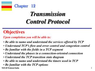
Parabola Focus Parabolic Reflective Antenna (The Dish!) Axis
Parabola Focus Parabolic Reflective Antenna (The Dish!) • Used for terrestrial and satellite microwave • On Transmission: Source placed at the focus will produce waves that get reflected from parabola parallel to the parabola axis • Creates a (theoretically) parallel beam to the parabola axis that does not spread (disperse) in space ( Zero radiation off axis) • In practice, some divergence (dispersion) occurs, because source at focus has a finite size (not exactly a point!) • On reception: Only signal from the axis direction is concentrated at focus, where detector is placed. Signals from other directions miss the focus ( Zero o/p off axis) • i.e. Directionality in both TX, RX operation • The larger the antenna (in wavelengths) the better the directionality High frequency is advantageous
Antenna Gain, G • A measure of directionality of the antenna • Power output in a given direction compared to that produced by a perfect isotropic antenna • Can be expressed in decibels (dB, dBi) (i = relative to isotropic) • Increased power radiated in one direction causes less power radiated in other directions (Total power is fixed) • Gain Gq depends on the effective area (Ae) of the antenna: • Depends on size and shape of the antenna • The Radiation pattern