Download
1 / 40
420 likes | 722 Views
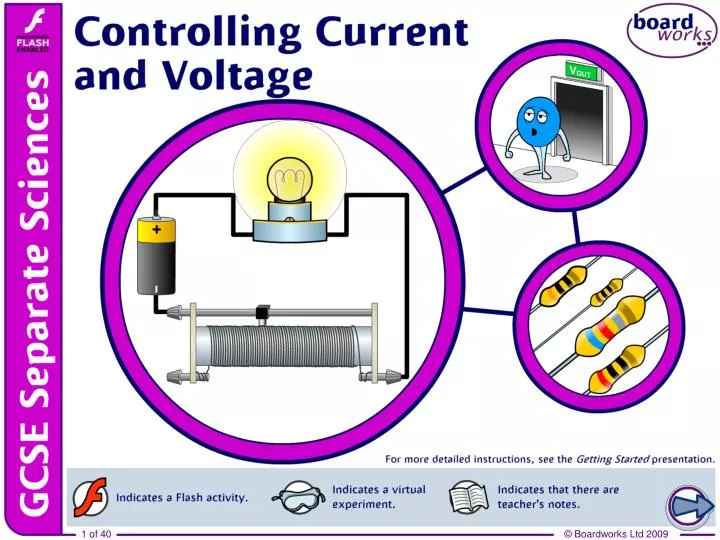
Controlling current and voltage. Resistance revision. Variable resistors. A variable resistor, also known as a rheostat, allows the resistance of a circuit to be varied. slider. thick bar. coil. variable resistor symbol. variable resistor.

E N D
Variable resistors A variable resistor, also known as a rheostat, allows the resistance of a circuit to be varied. slider thick bar coil variable resistor symbol variable resistor A variable resistor has two potential paths for current: one along a short, thick bar; another along a thin long coil. The slider is a mobile point of contact between these two routes, and its position determines the path of the current.
Ohm’s Law Ohm’s Law links current, voltage and resistance: voltage (V) = current (I) × resistance (R) Volts (V) Amps (A) Ohms (Ω) Ohm’s Law explains why resistance helps to control the current and voltage in a circuit. Any changes in resistance will have a knock-on effect on both the current and voltage. A formula triangle can be used to rearrange this equation. ×
Ohm’s Law practice questions A filament lamp has a current of 20A running through it, with a potential difference of 100V across it. What is the resistance of the filamentin the bulb? V 100V = = 5Ω V = I ×R R = I 20A Calculate the current flowing through a 230V kettle element which has a resistance of 57.5Ω. V 230V V = I × R I = = = 4A R 57.5Ω
Voltage–current graphs Voltage–current graphs are a simple plot of voltage, on the x-axis, against current, on the y-axis. current (A) Ohm’s Law tells us that the gradient of a V–I graph can be used to calculate resistance: voltage (V) change in current change in voltage voltage current gradient = resistance = 1 gradient Therefore: resistance = with these axes. Voltage–current graphs can vary greatly in form depending on the properties of the substance conducting electricity.
Calculating resistance from line graphs Calculate the resistance of these copper and nichrome wires. copper 4 4 nichrome 2 2 current (A) 0 0 5 10 15 5 10 15 0 20 0 20 voltage (V) voltage (V) 1 gradient change in current change in voltage resistance = gradient = copper: gradient = 2 ÷ 5 = 0.4 R = 1 ÷ 0.4 = 2.5Ω nichrome: gradient = 2 ÷ 10 = 0.2 R = 1 ÷ 0.2 = 5Ω
Different types of V–I graph While a resistor produces a constant resistance, and thus a straight line graph, other components show a variation in resistance at different levels of current and voltage. Such variation in resistance leads to a curved V–Igraph. current (A) A light bulb has a curved graph: it warms up as more electricity passes through it, increasing resistance. voltage (V) Such components are non-Ohmic – they do not obey Ohm’s Law.
V–I graphs for diodes A diode is a component that stops current flowing in one direction, but allows it to flow readily in the other, providing it is over a certain voltage. What would a V–I graph for a diode look like? current (A) voltage (V)
Understanding voltage Voltage is an electrical pushing force. The voltage of a cell describes how much electrical potential energy it gives the electrons: this pushes them around a circuit. When voltage is measured across a component it records the difference in electrical potential energy between the two sides of the component. This is also known as the potential difference. Thus the voltmeter reading of 4V tells us that there is 4V more electrical potential energy on one side of the resistor than the other. 4.0
Controlling voltage Imagine your alarm clock’s battery is flat. It requires 4V to run successfully, but you only have a 6V battery. This will overload its circuitry. However, you do have a selection of fixed resistors. How can these resistors help you to run the alarm clock from the battery without damaging it?
Series resistors and potential difference If two resistors are connected in series with a power supply, then the voltage is shared out between them. 6V 2.0 4.0 10Ω 20Ω The voltage is divided between components in proportion to their resistance. Thus the larger resistor has a larger share of the power supply voltage.
What is a potential divider? This principal can be used to power the alarm clock. VIN 6V The clock itself has a resistance of 20Ω. When placed in series with a 10Ω resistor, the battery’s voltage is split between the resistor and clock in a 2:1 ratio. 2V 4V 10Ω 20Ω The voltage across the resistor is 2V, while the voltage across the clock is 4V. The clock can now run safely. A circuit that splits the voltage between components, to produce a specific output voltage, is a potential divider.
Drawing potential dividers A potential divider uses series resistance to produce an output voltage (VOUT) that differs to the input voltage (VIN). Potential dividers are drawn in a slightly different way to other circuits. VIN 6V The distance between the horizontal lines represents the potential difference between different parts of the circuit. R1 10Ω VOUT 4V This arrangement is designed to visually demonstrate the change in potential difference across the resistors. R2 20Ω 0V 0V potential divider diagram
The potential divider equation The output voltage (VOUT)of a potential dividerdepends on the size of the resistors, and also the input voltage (VIN). VOUT can be calculated using the potential divider equation: VIN R2 (R1 + R2) VOUT = VIN× R1 VOUT VOUT and VIN are measured in volts (V). R2 R1 and R2 are measured in ohms (Ω). 0V 0V
Potential divider questions Calculate the output voltage, VOUT, for this potential divider. R2 (R1 + R2) 10V VOUT = VIN× 15Ω R1 60 15 + 60 = 10 × VOUT 60 75 = 10 × R2 60Ω = 10 × 0.8 0V 0V = 8V
Potential divider questions Calculate the output voltage, VOUT, for this potential divider. R2 (R1 + R2) 10V VOUT = VIN × 300 75 + 300 R1 75Ω = 10 × VOUT 300 375 = 10 × 300Ω R2 = 10 × 0.8 0V 0V = 8V
Potential dividers with a variable output If a variable resistor is used in a potential divider,VOUT becomes variable. VIN If R1 is a variable resistor… VOUT is low when the resistance of R1 is high. R1 VOUT R2 0V 0V R1 has a high proportion of the resistance, and thus a high proportion of the voltage.
Potential dividers with a variable output What happens when R2is a variable resistor? VIN R1 In this arrangement, the relationship between the resistance of the variable resistor and VOUT inverts. VOUT R2 0V 0V VOUT is high when resistance of R2 is high. R2 has a high proportion of the resistance and thus a high proportion of the voltage is at VOUT.
Semiconductors A semiconductor is a material which has electrical properties somewhere between an insulator, such as wood, and a conductor, such as iron. Semiconductors are usually made from silicon. Uses for semiconductors include: computer processor light dependent resistor light emitting diode Some semiconductors are able to vary their conductivity in response to changes in temperature or light intensity.
LDRs: light and resistance The resistance of a light dependent resistor(LDR)is not fixed. It is dependent on the intensity of incident light. An LDR has a high resistance in the dark but a low resistance in the light. LDR symbol The graph shows how the resistance of an LDR decreases as the light intensity increases. resistance (k) This means that LDRs can be used in light sensing circuits, because their output is dependent on the light conditions. light intensity
Thermistors: temperature and resistance The resistance of a thermistor varies depending on temperature. thermistor symbol It has a high resistance when cold but a low resistance when hot. This is unusual, as resistance normally increases with increasing temperature. Thermistors are useful in the sensor circuits of a thermostat, as their output varies with temperature fluctuations. resistance (k) temperature (°C)
Semiconductors as sensors 10 V The combination of a potential divider and a thermistor creates a temperature sensor. R1 VOUT The thermistor’s resistance will vary with temperature, resulting in a VOUT that is temperature dependent. R2 thermistor 0 V 0 V To produce a light sensor, replace the thermistor with an LDR. If the thermistor is in the R2 position, VOUT will be high at low temperatures, as the thermistor’s resistance will be high relative to R1. How will VOUT change if the thermistor is in the R1 position?