Download
1 / 19
190 likes | 209 Views
Intro to NI Multisim 10.1. Op Amps, Diodes tom epplin: tje3@cec.wustl.edu. Getting Started with Multisim (CEC). > Engineering > NationalInstruments Multisim 10.1. Getting Started with Multisim (CEC). Adding Multisim Components. > Place Component. Adding Multisim Components. > Group

E N D
Intro to NI Multisim 10.1 Op Amps, Diodes tom epplin: tje3@cec.wustl.edu
Getting Started with Multisim (CEC) • > Engineering • > NationalInstruments • Multisim 10.1
Adding Multisim Components • > Place • Component
Adding Multisim Components • > Group • Basic
Adding Multisim Components • > Capacitor • 300nF • Ok (Objects may be rotated using Edit -> Orientation)
Adding Multisim Components • > Place • Wire (or Ctrl+Q) (Note that red dots appear where successful junctions have been established)
Adding Multisim Components Don’t forget to place an appropriate reference ground: • > Place • Component • Sources • Power_Sources • Ground
Example Problem 1: Op Amp V2 V3 Output Input V1
Example Problem 1: Op Amp • Solving manually: V1 = (12V)(1kΩ/3kΩ) = 4V V2 = V1 = 4V (12V – 4V)/3kΩ = (4V – V3)/6kΩ V3 = -12V
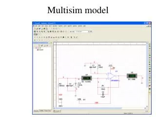
Example Problem 1: Op Amp • Solving using Multisim: • Compare voltages in circuit using an oscilloscope: • > Simulate > Instruments > Oscilloscope • Attach oscilloscope terminals across voltages to be compared:
Example Problem 1: Op Amp • Solving using Multisim: • Double-click on the oscilloscope to bring up its display, and hit the green play button in the Multisim toolbar
Example Problem 1: Op Amp V3 = -12V
Example Problem 2: Diode V1 Output Input
Example Problem 2: Diode • Solving manually: • Try top diode conducting: • Then, in ideal case (no loss through diode), V1 ≈ 3V • If V1 = 3V, then the middle and bottom diodes are not forwards-conducting • …No contradictory assumptions, and all voltages complicit V1 ≈ 3V
Example Problem 2: Diode • Solving using Multisim:
Example Problem 2: Diode V1 = 2.7V (real diode properties used)