Download
1 / 24
240 likes | 454 Views
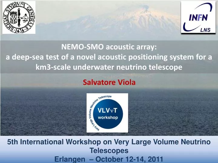
5th International Workshop on Very Large Volume Neutrino Telescopes Erlangen – October 12-14, 2011. NEMO-SMO acoustic array: a deep-sea test of a novel acoustic positioning system for a km3-scale underwater neutrino telescope. Salvatore Viola.

E N D
5th International Workshop on Very Large Volume Neutrino TelescopesErlangen – October 12-14, 2011 NEMO-SMO acoustic array: a deep-sea test of a novel acoustic positioning system for a km3-scale underwater neutrino telescope Salvatore Viola
The Submarine Multidisciplinary Observatory Project The SMO (Submarine Multidisciplinary Observatory) project aims at the construction, integration and joint operation of a submarine large bandwidth acoustic antenna at a depth of 3500 m, about 100 km off-shore South-East Sicily. • SMO goals: • Acoustic monitoring of the deep – sea environment • Deep-sea test of a novel acoustic positioning system for a km3-scale underwater neutrino telescope 3500 m depth 96 km off-shore
NEMO – SMO tower The SMO project consists of a 3D array of 18 acoustic sensors installed onboard the demonstrator NEMO – Phase II • NEMO Phase II detector • 8 floors plus a tower base • Floor length: 10 m • Distance between floors: 40 m • 32 optical modules ( 4 OMs/storey) • 18 acoustic sensors ( 2 sensors/ storey + 2 sensors @ tower-base) • 4 autonomous acoustic beacons (for acoustic positioning) • environmental sensors (compasses, CTD, Current-meter, C-Star) ShoreLaboratory in Capo Passero harbour 96 km 20 optical fibres 10 kV DC monopolar with sea return
Acoustic positioning system • The SMO acoustic array will provide the positioning of the NEMO Phase II detector • Requirements of neutrino telescope positioning system: • relative positioning accuracy : < 10 cm (less than PMT diameter) • absolute positioning accuracy: < 1 m to optimize pointing resolution • Key elements : • Long Baseline of acoustic emitters anchored in known and fixed positions • Array of acoustic sensors (hydrophones) moving with the mechanical structures Acoustic receivers at both end of each floor Measurament Technique: TDoA (Time Difference of Arrival): TEmit(Beacon) – TReceive(Hydro) 2. Geometrical Triangulation Independent Beacon (32 kHz, TSSC pulse) Monitoring Station 400 m
Acoustic Beacon The positioning system is based on the measurements of beacon pulses time of arrival (TOA) at a given acoustic receiver Each beacon transmits its TSSC (Time Spectral Spread Codes) sequence with a period of 6 sec, i.e. a pattern of 6 pseudo-random pulses (spaced by ~ 1 sec) that is different from the others. Beacon signal Amplitude: 180 dB re μPa @1 m Frequency : 32 kHz Pulse length: 5 ms Acoustic receivers at both end of each floor AutonomousBeacon (32 kHz, TSSC pulse) Monitoring Station ACSA autonomous acoustic beacon 400 m Tower Beacon 12VDC
Acoustic sensors SMID Hydrophone SMID Preamplifier Floor #1 ÷Floor #6 +Tower-base SMID Hydrophones + SMID preamplifiers (gain: +38 dB) Hydrophone +preamplifier sensitivity calibrated at NATO - URC (40 hydrophones) Measured differences ≤ ±2 dB Relative Hydrophone sensitivity variation with hydrostatic pressure at 20 kHz 400 Bar 300 Bar Radiation lobe 30 kHz 50 kHz Measured variations ≤ ±1 dB
Acoustic sensors Floor #7 FFR(Free Flooded Rings )Hydrophones + SMID preamplifiers (gain :+38 dB ) Receiving Response FFR - SX30 FFR +SMID preamp Fully compatibility with NEMO data acquisition chain See G. Larosa presentation
Acoustic sensors Floor #8 ECAP Piezo sensors + ECAP preamplifiers ECAP piezo + preamp ECAP piezo + preamp 30mm 21mm See A. Enzenhöfer presentation ECAP amp
The hydrophone data acquisition chain The hydrophones data acquisition chain is based on “all data to shore” philosophy, raw data are continuously transmitted to shore on a local internet network at the shore station. The acoustic signals are sampled by ADC and “labeled” with GPS time by the Floor Control Module (FCM ) off -shore Optical and Acoustic array synchronous and phased with absolute GPS time Data stream 32 bits @ 192 kHz 12 Mbps (2 hydrophones)
AcouBoard • The AcouBoard has been designed and realized by NEMO in collaboration with AGE Scientific (Lucca, Italy), by using professional audio technology components: • ADC 2 up to 4 channels ( 24 bit/192kHz, Max input 2 VRMS ) • EBU/AES-3 stereo compliant DIT (Digital Interface Transmitter) • Power 160 mA @ 5.3 VDC • ADC and DIT are driven by a clock signal (24.576 MHz) , given by FCM off-shore. • The technology developed for the SMO data acquisition system will be employed for the acoustic mezzanine designed for the KM3NeT Pre-Production Module (PPM). DIT Analogical signal coming from hydrophones 11 cm Link towards FCM off-shore (Data, Clock, Reset) ADC
Intrinsic electronic noise The intrinsic electronic noise of the whole NEMO-SMO data acquisition electronics has been measured at INFN –LNS. The measurement has consisted in to acquire the signals coming from the hydrophones’ preamplifiers with shorted input through the whole acquisition chain. Total power: -72 dB re 1 Vrms Noise floor: -145 dB re 1 V/√Hz
Acoustic system performances Equivalent noise of the NEMO-SMO data acquisition electronics Hydrophone+preamplifier (+38 dB) sensitivity: -172 dB re 1 V/Pa Expected underwater background noise
Underwater electronics latency measurement The accuracy on the measurement of the arrival time of acoustic signals on the hydrophones depends on the latency time of the underwater electronics. Waveform Generator trigger test signal GPS receiver digitalized test signal + GPS time digitalized test signal AcouBoard FCM Preamplifier Test signal: GPS Time eFCM Latency time = 39.529µs ±0.005 µs optical link (100 km) Test signal frequency: 48 kHz Resampling frequency: 192 MHz
Time calibration The GPS time is distributed off-shore through different optical link lengths. The time difference between the underwater time-stamping and the absolute GPS time was calculated. Waveform Generator trigger test signal PPS GPS receiver The differences between emission time of the test signal and the GPS time associated by the acquisition electronics to the corresponding audio samples has been measured for three different optical link lengths (±5 m) : 60m, 12710m and 25360m. Preliminary results are compatible with results obtained with the previous method. Systematics and statistical errors are under evaluation. digitalized test signal + GPS time digitalized test signal AcouBoard FCM Preamplifier GPS Time Extrapolated latency 39 µs errors under evaluation eFCM optical link Preliminary 10 20 30 40 50 60 70 80 90 Optical fibre length (km)
NEMO-SMO Data Transmission System Deep-sea detector INFN Shore Laboratory INFN-LNS 10 Gbps link Digitalization board Trigger Storage Main Storage GPS receiver Floor Control Module Underwater fibre Sensor data acquistion GPS time stamping Data transmission - fixed latency - known optical walk GARR-X (Italian Consortium for Research Network) GRID ? eFCM GPS clock transmission Data parsing/distribution
Conclusions New technology: New high pressure-calibrated hydrophones (in collaboration with SMID and NATO) New front-end electronics Synchronization with the detector master clock Underwater GPS time stamping All data to shore • Expected overall resolution for positioning few cm HIGH ENERGY PHYSICS Long term and real-time monitoring of high frequency acoustic background at different depths. Input for simulations of large scale acoustic detection Capo Passero Site: strong candidate for the km3 Cherenkov neutrino telescope • Test of sensors and electronics for a future deep sea acoustic neutrino detector • Test of DSP techniques (matched filters) to improve source identification and localization • Detection of neutrino-like signals produced by calibrated sources
Acoustic system performances Equivalent noise of the data acquisition electronics for SMID hydrophone + SMID preamplifier and ECAP piezoelectric + ECAP amplifier SMID Hydrophone+preamplifier(+38 dB) sensitivity: -172 dB re 1 V/Pa ECAP Hydrophone+amplifiersensitivity: -145 dB re 1 V/Pa SMID ECAP
Fixed latency between PPS and EFCM timing signals Frame TX Frame RX PPS-GPS
The KM3NeT Pre-ProductionModule (PPM) Acoustic System in the PPM - DOM (INFN LNS / Roma 1) All data to shore. Positioning and multidisciplinary science Stereo 192 kHz/24bit ADC GPS synch&time stamp Interfaced with Central Logic Board. Sensor readout: 1 external hydrophone (INFN or UPV-FFR) 1internal piezo (ECAP) 4 hydrophones ready Boards under production
Environmental sensors Floor #8 CTD ( Conductive-Temperature-Depth) Floor #5 DCS (Doppler Current Sensor) Floor #4 C-Star Floor #1 CTD ( Conductive-Temperature-Depth)
Compasses and tilt-meters In order to measure inclination and orientation of each tower floor a compass and tiltmeter board was placed inside the electronics vessel of each floor. These measurements, together with acoustic positioning, permit to estimate the tower position with the desired accuracy < 10 cm. Compass and tilt-meter Pitch axis Roll axis Compass and tilt-meter TCM 2.5
Environmental sensors: CTD A CTD (Conductivity-Temperature-Depth) probe will be installed on the 1st and on the 8th floor of the tower Floor #8 The CTD used is a 37-SM MicroCAT CTD manufactured by Sea Bird CTD Floor #1 CTD