Download
1 / 17
180 likes | 300 Views
Plasma Shape Reconstruction on-line Algorithm in Tokamaks. V.I. Vasiliev, Yu.A. Kostsov, K.M. Lobanov, L.P. Makarova, A.B. Mineev, D.V.Efremov Scientific Research Institute of Electrophysical Apparatus, St.-Petersburg, Russia, V.K. Gusev, R.G. Levin, Yu.V. Petrov, N.V. Sakharov

E N D
Plasma Shape Reconstruction on-line Algorithm in Tokamaks V.I. Vasiliev, Yu.A. Kostsov, K.M. Lobanov, L.P. Makarova, A.B. Mineev, D.V.Efremov Scientific Research Institute of Electrophysical Apparatus, St.-Petersburg, Russia, V.K. Gusev, R.G. Levin, Yu.V. Petrov, N.V. Sakharov A.F.Ioffe Physico-Technical Institute, St.-Petersburg, Russia JOINT MEETING OF THE 3rd IAEA TECHNICAL MEETING ON SPHERICAL TORI AND THE 11th INTERNATIONAL WORKSHOP ON SPHERICAL TORUS St. Petersburg State University, St. Petersburg, RUSSIA 3 to 6 October 2005
Plasma Shape Reconstruction Algorithm in Tokamaks Discussed here plasma shape reconstruction algorithm is based on using of current filaments to imitate plasma column and includes two steps. • At the first step location of the plasma current centroid is estimated roughly, using so-called plasma current density moments technique for two current filaments [1]. As results two pairs of the current filaments coordinates (r1,z1) and (r2,z2) can be calculated and they determine approximately plasma centroid location. • At the second step well known the fixed current filaments technique [2] is used to calculate plasma shape boundary. To allocate current filaments inside the vacuum vessel (in vicinity of plasma current centroid location) two points with coordinates (r1,z1) and (r2,z2), computed at the first step, are used.
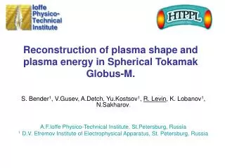
Globus-M cross-section flux loops (21) + two component probes (32)
First step algorithm If to define as “measuring contour“ a curve l, which passes through magnetic probes coordinate points, then plasma current density moments can be written as following [1] Here Ym is plasma current density moment of mthorder. fm and gm are functions that determine order of plasma current density moment and they satisfy to equations as follows In the case when plasma current distribution is approximated by two filament currents it is required fm and gm only up to 4th order to compute coordinates of two current filaments under condition that filament currents are equal each other.
First step algorithm (continue) Here measured value of normal component of field induction in the point of probe location with number “k”, measured value of tangential component of field induction in the point of probe location with number “k”, unknown current value in the jth current filament. Formulas described fm and gm functions are presented below as following f0 = 1; g0 = 0; f1 = z; g1 = -ln(r); f2 = r2; g2 = 2z; f3 = r2z; g3 = -(1/2)r2 + z2; f4 = -(1/4)r4 + r2z2; g4 = -r2z + 2/3 z3.
First step algorithm (continue) So, to compute coordinates of two current filaments it is necessary to calculate plasma current moments with using experimental data and with using current filaments approach and equate each other. Solving algebraic equation system with four unknown (r1,z1) and (r2,z2), current filaments coordinates can be found. Points (r1,z1) and (r2,z2) serve as the reference points to set plasma current filaments in vicinity of plasma current centroid to be used at second step.
Second step algorithm To reconstruct plasma shape boundary well known the fixed current filament technique [2] is used. In according with selected algorithm plasma is approximated by M current filaments with given coordinates (rj, zj) located inside plasma current centroid region. In the described here procedure current filaments are uniformly placed along ellipse with focal points (r1,z1) and (r2,z2). The value of ellipse minor semi-axis is adjusted to have more acceptable results. Unknown filament currents can be calculated by minimizing functional as follows
Second step algorithm (continue) computed value of normal component of field induction in the point of probe location with number “k”, computed value of tangential component of field induction in the point of probe location with number “k”, measured value of magnetic flux in the point of flux loop location with number “m”, computed value of magnetic flux in the point of flux loop location with number “m”, unknown current value in the jth filament, adjustable parameter, Here c1, c2 relative weighs
Second step algorithm (continue) • , and parameters are computed with using theoretical models of poloidal field coils and vacuum vessel and experimentally measured coil currents and loops voltages. • Poloidal field coil currents are measured during plasma discharge with Rogovsky coils and they are therefore known. • Vacuum vessel current distribution is calculated with using loop voltages measured by flux loops located on the vacuum vessel shell. Interpolating experimental measured data loop voltage and current value can be computed for each finite element of vacuum vessel. Minimizing residual functional filament currents can be calculated and then plasma column boundary can be reconstructed.
Application of plasma shape reconstruction technique in Globus-M data handling
Globus-M magnetic diagnostic complex consists of: • 32 two-components magnetic probes located on the vacuum vessel surface • 21 full-scale flux loops located on the vacuum vessel surface • Rogovsky coils to measure PF coils currents • Rogovsky coils to measure plasma current and sum Ip+Ivv flux loops (21) + two component probes (32) Globus-M cross-section
Application of plasma shape reconstruction techniquein Globus-M data handling (Continue) Preliminary adjustment of plasma shape reconstruction procedure in numerical experiments with theoretical models. Plasma evolution discharge scenario is simulated with using dynamic PET code with deformable plasma shape model. • Normal and tangential components of magnetic field induction ( ) relative to counter line with points of probes locations are numerically calculated. • Loop voltages that are used to estimate eddy current distribution in the vacuum vessel shell are calculated. • Test results of plasma shape reconstruction with using theoretical Globus-M model in the next picture.
Application of plasma shape reconstruction techniquein Globus-M data handling (Continue) PF2 PF2 PF1 PF1 HFC1 HFC1 CC1 CC1 CC2 CC2 HFC2 HFC2 PF3 PF3 VFC VFC CC3 CC3 OH OH OH OH CC3 CC3 VFC VFC PF3 PF3 HFC2 HFC2 CC2 CC2 CC1 CC1 HFC1 HFC1 PF1 PF1 PF2 PF2 Plasma equilibrium limiter configuration in Globus-M device; t=0.025 s, max difference = 7mm, Ip = 89.95 кА Plasma equilibrium diverter configuration in Globus-M device; t=0.050 s, , max difference = 17mm, Ip = 165.4 кА In total Using of 6 plasma current filaments gives acceptable results.
Application of plasma shape reconstruction techniquein Globus-M data handling (Continue) Results of plasma shape reconstruction in Globus-M experiments To demonstrate possibilities of the developed numerical plasma shape reconstruction code shot #10292 was taken as an example. To have better-fit results plasma column is simulated here with 9 currents filaments.
Reconstructed plasma shape boundary at limiter plasma discharge stage. • case with c1=1, c2=0; • case with c1=0, c2=1.
Reconstructed plasma shape boundary at divertor plasma discharge stage. • case with c1=1, c2=0; • case with c1=0, c2=1.
Conclusion Developed here plasma shape reconstructed algorithm can be useful in time between shots to analyse output data of plasma discharges. Proposed algorithm can be used as on-line algorithm in a feedback plasma shape control. References [1] Yasin I.V. PhD. Thesis, Kharkow, 1999. [2] Ogata A., Aicawa H., Suzuki Y., “Accuracy of plasma displacement measurements in a tokamak using magnetic probes,” Jap. J. Appl. Phys., no. 16,1, pp. 185-188, 1977.